INSTALLATION AND STARTUP GUIDE SPNDNT Network Processor IMPORTANT NOTICE: Several settings are mandatory to ensure the processor will connect and operate properly with a network and other processors. See page 11 for details. A trademark of Audinate Pty Ltd. Fill in for your records: Serial Number: Purchase Date: Rio Rancho, NM, USA www.lectrosonics.
ASPEN Digital Processor 2 LECTROSONICS, INC.
Installation and Quick Start Guide Important Safety Instructions This symbol, wherever it appears, alerts you to the presence of uninsulated dangerous voltage inside the enclosure -- voltage that may be sufficient to constitute a risk of shock. This symbol, wherever it appears, alerts you to important operating and maintenance instructions in the accompanying literature. Please read the manual.
ASPEN Digital Processor Table of Contents IMPORTANT NOTICE:.......................................................... 1 Important Safety Instructions............................................... 3 IMPORTANT NOTICE:.......................................................... 4 Overview.................................................................................. 5 What is Dante?..................................................................... 5 The Role of the SPNDNT Processor.......................
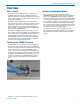
Installation and Quick Start Guide Overview What is Dante? Audinate’s patent pending Dante™ technology is a flexible Internet Protocol (IP) and Ethernet based digital AV network technology that eliminates the many bulky cables needed to provide point-to-point wiring for analog AV installations. With Dante, existing infrastructure can be used for high performance audio as well as for ordinary control, monitoring or business data traffic.
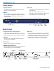
ASPEN Digital Processor Front Panel Headphone Monitor Status LEDs Standard 1/4 inch jack and level control. Drives both channels of stereo headphones. USB Port Standard USB connector for the setup and control from a computer using Windows XP, Vista or Windows 7 operating system. The USB port is also used for firmware updates.
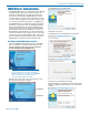
Installation and Quick Start Guide USB Driver Installation The ASPEN Device Installer opens. The ASPEN USB drivers are installed from the ASPEN Installation Disk, which comes with each device, by running the ASPEN Device Installer. Normally this is done before connecting an ASPEN device to the PC for the first time, but it can be done afterwards if necessary. The driver installation only needs to be done once on each PC that will be connected to an ASPEN unit.
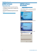
ASPEN Digital Processor ASPEN Software ASPEN Control Panel ASPEN processors are set up and monitored using the ASPEN Control Panel program. The software will run on Windows 7, Windows Vista® and Windows XP® operating systems. Use the disk included with every processor to install the software, or download the installer from the web site at: ASPEN Software Installation NOTE: Uninstall previous version before installing the software. Insert the disk into the drive and wait for the opening screen to appear.
Installation and Quick Start Guide The End User License Agreement screen appears. Click on I Agree, then on Next to continue. Click on Next to confirm the installation and continue. When the installation is complete the final screen will appear. Click on Close to finish the installation. It is usually best to accept the default folder for the installation. Click on Next to continue.
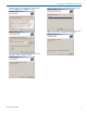
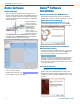
ASPEN Digital Processor Dante Software Dante Controller This is a second software package needed to route network audio signals between the SPNDNT and other nodes on a Dante network. The software is downloaded from the Audinate web site and will run on Windows and Mac platforms. Dante Controller is used to assign the transmit and receive signals between multiple Dante devices.
Installation and Quick Start Guide Mandatory Settings Set up the system in the Switched Mode in the Network Config screen in Dante Controller. Once everything is set up and audio is flowing to and from the network, a second network and gigabit switch can be added and the mode can be changed to Redundant. Connect an SPNDNT Dante port to the computer either directly or through a gigabit switch.
ASPEN Digital Processor Hardware Connections Installing the chassis into a rack Install the chassis so that the cooling fan vent is not blocked. Mount with 4 rack screws using the appropriate mounting holes. Use nylon washers to prevent damage to the front panel’s finish when tightening the mounting screws. All ASPEN processors have internal switching power supplies that can tolerate voltages ranging from 100 to 240 VAC. Use an approved power cord with an IEC 60320 C13 connector.
Installation and Quick Start Guide ASPEN RS-232 Port Programmable Outputs Wiring Diagram ASPEN Device to PC Programmable outputs are used for several purposes: 1 TX 2 RX 3 ASPEN 4 RS-232 GND 5 Port 6 7 8 9 DCE pin functions Female jack 1 2 3 4 5 6 7 8 9 DCD RX TX DTR GND DSR RTS CTS RI Host Serial Port (PC) Male jack Female connector Crestron® RS-232 Port Wiring 1 TX 2 RX 3 4 ASPEN RS-232 GND 5 Port 6 7 8 9 Female jack 1 2 RX 3 TX 4 5 GND 6 7 8 9 Wiring Diagram Male connector indicate the curr
ASPEN Digital Processor Network and PC Connections Server The SPNDNT processor must be the Master at the top of the ASPEN stack to synchronize the system and network clocks.
Installation and Quick Start Guide Secondary network for redundancy ork Audio Transport CAT-6 cable RS-232 ports for external control system SPN 1624 GND PROG IN DATECODE OUTPUTS +5V INPUTS PROG OUT S/N LABEL Adaptive Proportional Gain Mixing US Patent 5,414,776 ASPEN PORTS GND PROG IN +5V OUTPUTS INPUTS PROG OUT 100-240V 50/60Hz 30W RS-232 ETHERNET Supplied ASPEN cables CAT-5 or better cables To front panel USB port Using Switched and Redundant Modes NOTE: See page 11 for instructi
ASPEN Digital Processor System Setup Examples Basic Configuration X = INPUT O = OUTPUT This example illustrates the basic signal routing between two ASPEN subsystems connected via a Dante network. This setup creates a “full-duplex” connection where each ASPEN subsystem transmits and receives signals simultaneously as might be used to conduct conferencing between two meeting rooms. In this example, no local sound reinforcement is in use.
Installation and Quick Start Guide Set up the inputs for the microphones with the gain value set to achieve 0 dBu on the meter during speech. Select mixer Inputs tab Audio level meter Route the microphone inputs to Mix 1 and Mix 2 on subsystem A and Mix 3 and Mix 4 on subsystem B under the matrix tab (subsystem A shown). Select mixer Select the source signal to be delivered to the outputs.
ASPEN Digital Processor Using the AEC on Network Connections When the Trio or Conference processor is used in the ASPEN subsystem, the AEC (acoustic echo canceller) can be applied to the network connections to suppress echo caused by acoustical coupling between microphones and loudspeakers. In this example, a local sound reinforcement system is in place, which further increases the potential echo. (1->1, 2->2...) (1->1, 2->2...) (1->1, 2->2...) (1->1, 2->2...
Installation and Quick Start Guide Assign the two microphone inputs to Mix Buses 16 and 17 to be used for local sound reinforcement. Make the assignments under the SPNTrio matrix tab. Select SPNTrio Matrix tab Assign the AEC output to Mix 1, which is the signal source for the audio sent to the other ASPEN system via the network. Select SPNTrio Matrix tab Assign the two microphone inputs to Mix Bus 47 to deliver audio to the other ASPEN system via the network.
ASPEN Digital Processor Assign the Dante receive channel 1 to Mixes 16 and 17 to deliver the audio from the network into the local sound system under the SPNDNT Matrix tab. Select SPNDNT Matrix tab Assign Dante receive channel 1 to Mix 48 to deliver the audio from the network to the AEC to provide a reference signal for echo cancellation. Select SPNDNT Matrix tab Subscribe to the transmit channels from the opposite ASPEN subsystems to flow audio back and forth between the ASPEN systems.
Installation and Quick Start Guide Rio Rancho, NM 21
ASPEN Digital Processor Multiple Site Conferencing This example illustrates how multiple ASPEN subsystems can be set up identically and use Dante channels to transmit and receive audio. 22 LECTROSONICS, INC.
Installation and Quick Start Guide Route the inputs as follows: • In 1 to Mix 1 and Mix 5 • In 2 to Mix 2 and Mix 5 In this example, Mixes 1 and 2 are routed to the local sound system in a mix-minus pattern. Mix 5 delivers the audio from the local microphones into the Dante network. Select SPNTrio Set up the inputs for the microphones connected to the SPNTrio. Adjust the gain so the level is close to 0dBu during normal speech.
ASPEN Digital Processor In this example, the processors in the subsystems all subscribe to receive audio from the other two subsystems on Dante transmit channels 1 and 2. This setup is also an effective solution for signal routing in room combining systems. A system configuration like this would be an ideal solution for multi-site Telepresence video conferencing by allowing a full-duplex, system wide audio signal flow.
Installation and Quick Start Guide Rio Rancho, NM 25
ASPEN Digital Processor FCC Part 15 Compliance This device complies with Part 15 of the FCC Rules. Operation is subject to the following two conditions: (1) This device may not cause harmful interference, and (2) this device must accept any interference received, including interference that may cause undesired operation. CAUTION: Changes or modifications not expressly approved by Lectrosonics, Inc. could void the user’s authority to operate the equipment.
Installation and Quick Start Guide Service and Repair If your system malfunctions, you should attempt to correct or isolate the trouble before concluding that the equipment needs repair. Make sure you have followed the setup procedure and operating instructions. Check the interconnecting cables and then go through the Troubleshooting section in this manual.
LIMITED THREE YEAR WARRANTY The equipment is warranted for three years from date of purchase against defects in materials or workmanship provided it was purchased from an authorized dealer. This warranty does not cover equipment which has been abused or damaged by careless handling or shipping. This warranty does not apply to used or demonstrator equipment. Should any defect develop, Lectrosonics, Inc. will, at our option, repair or replace any defective parts without charge for either parts or labor.