
User Manual


SPNCWB
LECTROSONICS, INC.
8
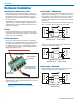
Audio Inputs – Unbalanced
Unbalanced audio sources include items such as con-
sumer VCR’s, DVD players, etc., which can be connect-
ed with either 2-wire or 3-wire cables. The (+) terminal
of the source is connected to the (+) terminal of the
processor. The shield and (–) connections are made as
shown here.
Three wire cables should have the shield connected to
the (–) connector at the source end of the cable.
Processor
Unbalanced source to
ASPEN input – 3-wire cable
Source
Shield
Two wire cables should have a jumper between the
processor (–) input and ground.
Processor
Unbalanced source to
ASPEN input – 2-wire cable
Source
Shield
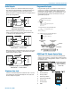
Audio Inputs – Balanced
Balanced audio sources connect to the processor in-
puts in a straight “pin to pin” configuration.
Processor
Balanced source to
ASPEN input
Source
Shield
Installing the chassis into a rack
Install the chassis so that the cooling fan vent is not
blocked. Mount with 4 rack screws using the appropri-
ate mounting holes. Use nylon washers to prevent
damage to the front panel’s finish when tightening the
mounting screws.
All ASPEN processors have internal switching power
supplies that can tolerate voltages ranging from 100
to 240 VAC. Use an approved power cord with an IEC
60320 C13 connector.
Cables
It is recommended that you use lacing bars for cable
strain relief when mounting in a rack. Use only profes-
sional audio cable with proper shielding – typically, two
conductor plus ground/shield.
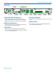
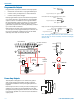
Audio Connectors
The analog audio inputs and outputs are connected
through 5-pin de-pluggable connectors. Strip the insula-
tion back 1/8 to 3/16” but do not tin (apply solder to)
the leads. Insert the wire into a de-pluggable connec-
tor, leaving less than 1 mm of bare wire exposed, then
tighten the retaining screw.
Caution: Do not overtighten the screws.
5-pin depluggable
connector
Do not leave more than
1 mm of exposed wire
beyond the connector.
Do not apply
solder to leads
Retaining Screw
(Do not overtighten)
Note the labeling on the rear panel for the positive and
negative leads. Ground is shared between two connec-
tions (the center pin).
Note: ASPEN processors do not have a “pin 1
problem.” Inputs and outputs are true differential
connections.
Hardware Installation