
User Manual

Installation and Startup Guide
Rio Rancho, NM
11
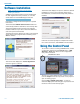
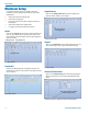
Connecting the Master for the First Time
NOTE: Install ASPEN software before connecting
the Master unit to a computer.
The computer operating system will automatically de-
tect and configure a USB port for the Master unit when
it is connected and turned on the first time. Wait for the
screen message that advises that the new device has
been configured and is ready for use.
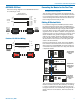
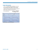
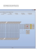
Cabling Of Stacked Units
In a stacked configuration, ASPEN processors must
be interconnected as shown here. The ASPEN bus is
bidirectional, allowing data and audio to be propagated
forward and backward through a single cable connec-
tion. Each Slave unit in a stack gathers data and audio
signals from the unit below it, adds its own signals and
passes the total on to the unit above it. At the top of the
stack, the Master unit gathers all signals from below,
adds its own and then sends the total back down the
bus to all Slave units below it. This architecture allows
all Slave units to have access to the mixing data and
audio in all 48 final mixes.
Each circuit board has an upper and a lower ASPEN
bus connector. Since there are two circuit boards in a
2RU unit such as the SPNTWB, the circuit boards are
connected in the same manner as if they were each in
a separate chassis.
1RU SPNCWB
configured as
Master
2RU SPTWB
configured as
intermediate
Slave
1RU SPN16i
configured
as lowermost
Slave
ASPEN PORT
The processors automatically configure themselves for
Master and Slave status as determined by the cabling.
If a unit is connected to another unit above it through
the upper connector, it is automatically configured as a
Slave. If there is no unit above it, then it becomes the
Master.
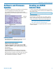
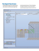
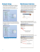
ASPEN RS-232 Port
Here is the wiring diagram for the ASPEN RS-232 Port
for connecting to a PC.
1
2
3
4
5
6
7
8
9
1
2
3
4
5
6
7
8
9
DCD
RX
TX
DTR
GND
DSR
RTS
CTS
RI
TX
RX
GND
Host
Serial
Port
(PC)
ASPEN
RS-232
Port
Wiring Diagram
ASPEN Device to PC
DTE pin
functions
Female
connector
Male
connector
DCE pin
functions
Female
jack
Male jack
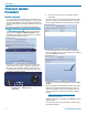
Crestron
®
RS-232 Port Wiring
1
2
3
4
5
6
7
8
9
1
2
3
4
5
6
7
8
9
RX
TX
GND
TX
RX
GND
Crestron
RS-232
Port
ASPEN
RS-232
Port
Wiring Diagram
Female
connector
Male
connector
Female jack
Male jack