
User Manual

Stereo Portable Digital Recorder
Rio Rancho, NM
19
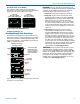
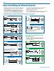
Line Level Signals
The normal wiring for line level signals is:
• Signal Hot to pin 5
• Signal Gnd to pin 1
• Pin 4 jumped to pin 1
This allows signal levels up to 3V RMS to be applied
without limiting.
If more headroom is needed, insert a 20 k resistor in
series with pin 5. Put this resistor inside the TA5F con-
nector to minimize noise pickup.
See Fig. 8 on
previous page
Line Level
Normal Wiring
Line Level
More Headroom
(20 dB)
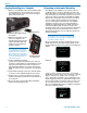
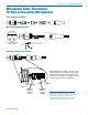
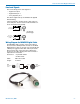
Wiring Diagram for MCAES3 Digital Cable
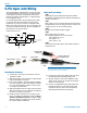
The MCAES3 cable is used to connect the output of
the Lectrosonics SPDR portable recorder to the AES3
digital input of a mixer or recorder. It is constructed with
a TA5F jack, rugged coaxial cable and a 3-pin female
XLR connector. The connectors have soldered con-
nections to the cable, allowing them to be serviced or
replaced if the need arises.
Connectors: • 5-pin TA5F female
• XLR-3 female
Cable: RG-174U coaxial
Length: 18 inches
5
4
3
2
1
CH 2
-
CH 2
+
CH 1
-
CH 1
+
GND
PIN
3
-
2
+
1 GND
PIN
3
12
XLRF
Vie
wed from
outside
T
A5F
Vie
wed from
outside
3
1
2
4
5