
User Manual

SPDR
LECTROSONICS, INC.
12
Operating Instructions
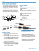
Recording in Analog Mode
1) Connect microphone or audio source (p. 7).
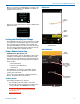
2) In Input menu, set Input Type to Analog:
When the Input Type is set to Analog, this menu item
will allow you to adjust the input gain. The two tricolor
audio level indicator LEDs on the top of the SPDR pro-
vide a visual indication of each analog audio signal level
entering the recorder. The LEDs will glow either red or
green to indicate audio levels, as shown in the following
table.
Signal Level LED
Less than -20 dB
Off
-20 dB to +0 dB Green
+0 dB and up
Red
3) In Input menu, set Input Level.
When setting input level in Analog Input Type, it is best
to go through the following procedure before recording.
1) With fresh batteries in the SPDR, power the
unit on.
2) Prepare the signal source(s). Position
microphone(s) the way it will be used in actual
operation and have the user speak or sing at the
loudest level that will occur during use, or set the
output level of the instrument or audio device to the
maximum level that will be used (see signal level
chart below).
3) Press MENU/SEL to select which input to adjust.
Adjust the input gain with the UP and DOWN arrow
buttons so that the input LED glows green during
the loudest peaks in the audio. The LED will turn
red if the peak is being limited in the preamp.
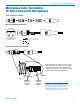
4) In Input menu, set Stereo Mode.
Linked:
The limiters on both channels operate together to pre-
serve the balance of the stereo image. Both red LEDs
will come on at the same time, along with the “L” block
on the LCD, even when limiting is only required on one
channel, but the audio bar graph meters will operate
independently.
Independent:
Use this mode if you are recording two separate
sounds/voices, and each input will have a separate
limiter.
1
2
44
36
Input Level
-40 -20 +0
Input Level
-40 -20 +0
38
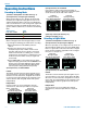
Input Level:
Input Type: Analog
Stereo Mode: Independent
Input Level:
Input Type: Analog
Stereo Mode: Linked
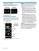
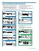
5) In Input menu, set LF Rolloff:
Low frequency audio content may be desirable or
distracting, so the point at which the roll-off takes place
can be set to 35, 50, 70, 100, 120 or 150 Hz.
1
2
LF Rolloff
70
Hz
Hz
120
LF Rolloff
70 Hz
LF Rolloff:
Input Type: Analog
Stereo Mode: Independent
LF Rolloff:
Input Type: Analog
Stereo Mode: Linked
5) Set output level (HP Volume p. 8).
6) Begin recording (p. 13).
Recording in Digital Mode
1) Connect microphone or audio source (p. 7).
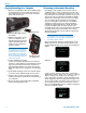
2) In Input menu, set Input Type to Digital:
When the Input Type is set to Digital, the two tricolor au-
dio level indicator LEDs on the top of the SPDR will be
blue for a signal above -40 and off otherwise. In Digital
mode, the input is AES 3 compatible. In this configura-
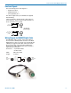
tion, pin 4 is + and pin 1 is -.
1
2
Input Level
-40 -20 +0
[AES INPUT]
Input Level
-40 -20 +0
[AES INPUT]
Input Level:
Input Type: Digital
Stereo Mode: Independent
Input Level:
Input Type: Digital
Stereo Mode: Linked
3) In Input menu, set Stereo Mode.
Linked:
The limiters on both channels operate together to pre-
serve the balance of the stereo image. Both red LEDs
will come on at the same time, along with the “L” block
on the LCD, even when limiting is only required on one
channel, but the audio bar graph meters will operate
independently.
Independent:
Use this mode if you are recording two separate
sounds/voices, and each input will have a separate
limiter.