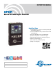
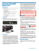
INSTRUCTION MANUAL SPDR Stereo Portable Digital Recorder Quick Start Steps 1) Install batteries (or connect to external power)and turn the power on (p. 5). 2) Insert microSDHC memory card and format it with the SPDR (p. 6). 3) Jam to a timecode source, if needed.(p. 10). 4) Connect microphone or audio source (p. 7). 5) Set input type and level, if analog source (p.12). 6) Select record mode (p. 11). 7) Set output level (HP Volume p. 10). 8) Begin recording (p.8).
SPDR 2 LECTROSONICS, INC.
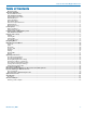
Stereo Portable Digital Recorder Table of Contents Quick Start Steps...................................................................................................................................................................................1 Technical Highlights................................................................................................................................................................................4 Broadcast Wave Format...........................................
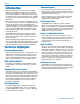
SPDR Introduction The second recorder from Lectrosonics, the SPDR (Stereo Portable Digital Recorder) delivers advanced technology and features, including stereo mode with two channels available. As a backup recorder in a bag, the recorder is small, yet packed with features, including extended run time, optional external power and higher sample rates.
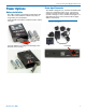
Stereo Portable Digital Recorder Power Options Power Input Connector Battery Installation The audio recorder is powered by two AA Lithium batteries. Zinc-carbon batteries marked “heavy-duty” or “long-lasting” are not adequate. Push outward on the battery compartment door and lift it to open. The SPDR is designed to be used with the DCR12/A5U external (or equivalent) power source.
SPDR Preparing a MicroSDHC Memory Card Compatible Cards We have tested a wide variety of cards and these performed the best with no issues or errors. • Lexar 16GB High Performance UHS-I (Lexar part number LSDMI16GBBNL300).
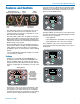
Stereo Portable Digital Recorder Features and Controls AES Dual Channel or Analog Single Channel Input Analog Input LEMO TC Input The main functions of SPDR, Record, Stop Recording, Playback are revealed by the status indicator. Both the status indicator and soft buttons change to accommodate the current SPDR function.
SPDR Powering On Press and hold the Power Button until the Lectrosonics logo appears on the LCD. Record icon blinks Menu i Powering Off Recording info REC Power can be turned off by holding the Power Button in and waiting for the countdown. The Power Button will not work while the unit is recording (stop recording first before powering down) or if the SPDR has been locked (unlock the recorder first).
Stereo Portable Digital Recorder Timecode... SEL BACK Navigating Menus TC Jam JAM NOW Frame Rate Use Clock Inputs... SEL Plug in time code source and sync Use arrow keys to select Press frame rate of 30, 29.97, 25, function 24, 23.976, 30DF, or 29.
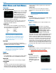
SPDR Main Menu and Sub Menus channel, but the audio bar graph meters will operate independently. Timecode Independent: TC Jam (jam timecode) When TC Jam is selected, JAM NOW will flash on the LCD and the unit is ready to be synced with the timecode source. JAM NOW Connect the timecode source and the sync will take place automatically. When the sync is successful, a message will be displayed to confirm the operation.
Stereo Portable Digital Recorder Takes/Play Backlight Takes/Play S S S S 1 1 1 1 T T T T 2 1 16 15 Choose to play the files based on scene and take. Use the arrows to scroll, MENU/SEL to select the file and the DOWN arrow to play. Bat Type Choose either Alkaline or Lithium AA battery type. The voltage of the installed batteries will be shown at the bottom. Remote File Naming File naming can be set as Sequence, Clock Time or Scene/Take. Use the arrows to scroll, MENU/SEL to choose.
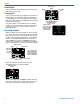
SPDR Operating Instructions Recording in Analog Mode 1) Connect microphone or audio source (p. 7). 2) In Input menu, set Input Type to Analog: When the Input Type is set to Analog, this menu item will allow you to adjust the input gain. The two tricolor audio level indicator LEDs on the top of the SPDR provide a visual indication of each analog audio signal level entering the recorder. The LEDs will glow either red or green to indicate audio levels, as shown in the following table.
Stereo Portable Digital Recorder Files/Play Choose to play files by the filename. File- 4) In Input menu, set LF Rolloff: Low frequency audio content may be desirable or distracting, so the point at which the roll-off takes place can be set to 35, 50, 70, 100, 120 or 150 Hz. LF Rolloff: Input Type: Digital Stereo Mode: Independent LF Rolloff 1 LF Rolloff: Input Type: Digital Stereo Mode: Linked LF Rolloff 2 [AES INPUT] [AES INPUT] 5) Set output level (HP Volume p. 8). 6) Begin recording (p. 13).
SPDR Copying Recordings to a Computer 1. Remove your MicroSD card from the SPDR by lightly pushing down on the card and, when released, the card should pop out of the recorder enough to gently remove the card. 2. Insert the MicroSD card into the adapter. Write Protect Tab Recordings can be reliably recovered even if the microSDHC memory card is accidentally removed or the battery dies while a recording is in progress.
Stereo Portable Digital Recorder Once set as desired, use MENU/SEL to navigate to the “GO” soft button and press the DOWN arrow button to begin the recovery process. iOS Version Length to recover? hh mm 08:10 GO Tap to play tone Recovery is nearly instantaneous. When completed, the display will show: RECOVERY SUCCESSFUL Select Mode Playback Volume Locking and Unlocking the Settings The LOCKED mode protects the recorder from accidental changes to its settings.
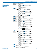
SPDR 5-Pin Input Jack Wiring Audio input jack wiring: The wiring diagrams included in this section represent the basic wiring necessary for the most common types of microphones and other audio inputs. Some microphones may require extra jumpers or a slight variation on the diagrams shown. PIN 1 Shield (ground) for positive biased electret lavaliere microphones. Shield (ground) for dynamic microphones and line level inputs.
Stereo Portable Digital Recorder Microphone Cable Termination for Non-Lectrosonics Microphones TA5F Connector Assembly Mic Cord Stripping Instructions 1 4 5 2 3 VIEW FROM SOLDER SIDE OF PINS 0.15" 0.3" Crimping to Shield and Insulation Strip and position the cable so that the clamp can be crimped to contact both the mic cable shield and the insulation. The shield contact reduces noise with some microphones and the insulation clamp increases ruggedness.
SPDR Input Jack Wiring for Different Sources In addition to the microphone and line level wiring hookups illustrated below, Lectrosonics makes a number of cables and adapters for other situations such as connecting musical instruments (guitars, bass guitars, etc.) to the transmitter. Visit www.lectrosonics.com and click on Accessories, or download the master catalog. A lot of information regarding microphone wiring is also available in the FAQ section of the web site at: http://www.lectrosonics.
Stereo Portable Digital Recorder Line Level Signals The normal wiring for line level signals is: • Signal Hot to pin 5 • Signal Gnd to pin 1 • Pin 4 jumped to pin 1 This allows signal levels up to 3V RMS to be applied without limiting. If more headroom is needed, insert a 20 k resistor in series with pin 5. Put this resistor inside the TA5F connector to minimize noise pickup. Line Level Normal Wiring See Fig.
SPDR Optional Accessories 26526 Wire belt clip DCR12/A5U External power source; interchangeable blades. MC70 line level adapter cable. Male 3.5 mm TRS to female TA5F; 14 inches long. Feeds line level signal to pin 5 on the TA5M input jack. MCAES3 Used to connect the output to the AES3 digital input of a mixer or recorder; TA5F jack to 3-pin female XLR connector P1354 dust and moisture plug for headphone/line output and timecode sync port. MC35 line level adapter cable.
Stereo Portable Digital Recorder External Power Supply: DCR12/A4U 90-240 VAC, 50/60 Hz input; 12 VDC (regulated), 400 mA max. output. Specifications Recording Storage media: MicroSD (HC type) File format: .wav files (BWF) iXML metadata A/D converter: 24-bit Sampling rate: 48 kHz or 96 kHz Recording modes/Bit rate: Sample Rate External DC Power Cords: 21425 6 ft. long power cord, coaxial to stripped and tinned leads. Coaxial plug: ID-.080”; OD-.218”; Depth- .5”. .475” . ” O.D .375 21472 6 ft.
SPDR This device complies with part 15 of the FCC Rules. Operation is subject to the following two conditions: (1) This device may not cause harmful interference, and (2) this device must accept any interference received, including interference that may cause undesired operation. NOTE: This equipment has been tested and found to comply with the limits for a Class B digital device, pursuant to part 15 of the FCC Rules.
Stereo Portable Digital Recorder Service and Repair If your system malfunctions, you should attempt to correct or isolate the trouble before concluding that the equipment needs repair. Make sure you have followed the setup procedure and operating instructions. Check the interconnecting cables and then go through the Troubleshooting section in this manual.
LIMITED ONE YEAR WARRANTY The equipment is warranted for one year from date of purchase against defects in materials or workmanship provided it was purchased from an authorized dealer. This warranty does not cover equipment which has been abused or damaged by careless handling or shipping. This warranty does not apply to used or demonstrator equipment. Should any defect develop, Lectrosonics, Inc. will, at our option, repair or replace any defective parts without charge for either parts or labor.