
User's Manual
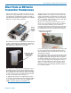


SMV Series
LECTROSONICS, INC.
14
Wiring Hookups for Different Sources
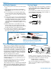
BALANCED AND FLOATING LINE LEVEL SIGNALS
*NOTE: If the output is balanced but center
tapped to ground, such as on all Lectrosonics
receivers, do not connect Pin 3 of the XLR jack
to Pin 4 of the TA5F connector.
TA 5F
PLUG
XLR JACK
Fig. 7
Compatible Wiring for Both Servo Bias Inputs and Earlier Transmitters:
Simple Wiring - Can ONLY be used with
Servo Bias Inputs:
Servo Bias was introduced in 2005 and all trans-
mitters with 5-pin inputs have been built with this
feature since 2007.
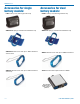
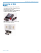
In addition to the microphone and line level wiring hook-
ups illustrated below, Lectrosonics makes a number of
cables and adapters for other situations such as con-
necting musical instruments (guitars, bass guitars, etc.)
to the transmitter. Visit www.lectrosonics.com and
click on Accessories, or download the master catalog.
A lot of information regarding microphone wiring is also
available in the FAQ section of the web site at:
http://www.lectrosonics.com
Hover over Support and click on FAQs. Follow the instructions
to search by model number or other search options.
SHIELD
TIP
PIN
5
4
3
2
1
SLEEVE
LINE LEVEL
RCA or 1/4” PLUG
A UDI O
1
2
3
4
5
T A5 F
PLUG
UNBALANCED LINE LEVEL SIGNALS
For signal levels up to 3V (+12 dBu) before limiting. Fully
compatible with 5-pin inputs on other Lectrosonics transmitters
such as the LM and UM Series. A 20k ohm resistor can be
inserted in series with Pin 5 for an additional 20 dB of
attenuation to handle up to 30V (+32 dBu).
Fig. 8
1
2
3
4
5
PIN
SHIELD
AUDIO
1
2
3
4
5
TA5F
PLUG
2.7 k
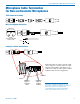
2 VOLT NEGATIVE BIAS 2-WIRE ELECTRET
Compatible wiring for microphones
such as negative bias TRAM models.
NOTE: The resistor value can range from 2k to 4k ohms.
Fig. 4
Fig. 11
4 VOLT POSITIVE BIAS 3-WIRE ELECTRET
NOTE: This servo bias wiring is not compatible with earlier
versions of Lectrosonics transmitters. Check with the factory
to confirm which models can use this wiring.
2 VOLT POSITIVE BIAS 2-WIRE ELECTRET
Simplified wiring for microphones
such as Countryman B6 Lavalier
and E6 Earset models and others.
NOTE: This servo bias wiring is not compatible with earlier
versions of Lectrosonics transmitters. Check with the factory
to confirm which models can use this wiring.
Fig. 9
Fig. 3 - DPA Microphones
DANISH PRO AUDIO MINIATURE MODELS
This wiring is for DPA lavalier
and headset microphones.
NOTE: The resistor value can range from 3k to 4 k ohms.
Same as DPA adapter DAD3056
Fig. 10
2 VOLT NEGATIVE BIAS 2-WIRE ELECTRET
Simplified wiring for microphones such as negative bias TRAM.
NOTE: This servo bias wiring is not compatible with earlier
versions of Lectrosonics transmitters. Check with the factory
to confirm which models can use this wiring.
Fig. 6
LO-Z MICROPHONE LEVEL SIGNALS
For low impedance dynamic mics or electret
mics with internal battery or power supply.
XLR JACK
Insert 1k resistor in series with pin 3 if attenuation is needed
Fig. 1
1
2
3
4
5
PIN
SHIELD
A UDI O
1
2
3
4
5
T A5 F
PLUG
3.3 k
1.5 k
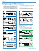
2 VOLT POSITIVE BIAS 2-WIRE ELECTRET
Compatible wiring for microphones such as
Countryman E6 headworn and B6 lavaliere.
Also see Fig. 9
4 VOLT POSITIVE BIAS 2-WIRE ELECTRET
Most common type of wiring for
lavaliere mics.
Fig. 2
WIRING FOR LECTROSONICS M152/5P
(N/C)
WHITE
RED
The M152 lavaliere microphone
has an internal resistor and can be
wired in a 2-wire configuration.
This is the factory standard wiring.
Fig. 5 - Sanken COS-11 and others
DRAIN (BIAS)
SOURCE (AUDIO)
SHIELD
4 VOLT POSITIVE BIAS 3-WIRE ELECTRET
WITH EXTERNAL RESISTOR
Also used for other 3-wire
lavaliere microphones that
require an external resistor.