
User Manual

Super-Minature Belt Pack Transmitter
Rio Rancho, NM
5
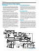
Signal Encoding and Pilot Tone
In addition to controlling the limiter, the DSP also en-
codesthedigitizedaudiofromtheA/Dconverterand
adds an ultrasonic pilot tone to control the squelch in
the receiver. A pilot tone squelch system provides a reli-
able method of keeping a receiver output muted (audio
mute) even in the presence of significant interference.
Whenthesystemisoperatinginthehybridmode,adif-
ferent pilot tone frequency is generated for each carrier
frequency to prevent inadvertent squelch problems in
multi-channelsytems.
Microprocessor Control
A microprocessor monitors user command inputs from
the control panel buttons and numerous other internal
signals. It works intimately with the DSP to ensure the
audio is encoded according to the selected Compatibil-
ity Mode and that the correct pilot tone is added to the
encoded signal.
Compatibility Modes
SM transmitters are designed to operate with Lectro-
sonics Digital Hybrid receivers and will yield the best
performance when doing so, however, due to the flex-
ibility of digital signal processing, the transmitter can
also operate in various compatibility modes for use with
Lectrosonics 200 Series, Lectrosonics 100 Series, IFB
andcertainnon-Lectrosonicsreceivers.Contactthe
Lectrosonics sales department for more information
aboutnon-Lectrosonicsreceivers.
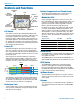
Control Panel
The control panel includes four membrane switches and
anLCDscreentoadjusttheoperationalsettings.Multi-
colorLEDsareusedtoindicateaudiosignallevelsfor
accurate gain adjustment and for battery status.
Wide-Band Deviation
±75kHzdeviationimprovesthesignaltonoiseratioand
audio dynamic range of a wireless system dramatically,
comparedtootherdesignsthatuse±30kHzto40kHz
deviation.Widedeviationcombinedwithahighpowered
transmitters makes a significant improvement in signal
to noise ratio and operating range.
Variable Power Output
Thisadvancedfeatureallowstheoperatortooptimize
the transmitter for maximum battery life, or for maximum
operating range. Power output is selected using the
LCD in a setup mode while the RF output of the trans-
mitter is turned off.
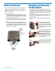
Battery Options and Operating Time
Switching power supplies convert regulated battery volt-
ages to operate various circuit stages with maximum
efficiency.
The firmware “remembers” the power status when a
battery fails, so the transmitter will be turned on auto-
matically when the battery is replaced and the previous
settings will be enabled.
Frequency Blocks
Lectrosonics established a “block” numbering system
yearsagotoorganizetherangeoffrequenciesavail-
ablefromthelowendat470MHzbandtotheupper
endat952MHz.Eachblock(except944)includes256
frequenciesin100kHzsteps,whichisthemaximum
switching range of the transmitters. Block 944 is a spe-
cialbandbetween944and952MHz.
Circulator/Isolator
The RF output circuit includes a one way circulator/iso-
latorusingamagneticallypolarizedferrite.Thisdevice
greatly reduces RF intermodulation produced when
multiple transmitters are used in close proximity to one
another (several feet apart). The isolator also provides
additional RF output stage protection against static
shock.