
User's Manual

SMV Series
LECTROSONICS, INC.
6
Controls and Functions
LCD Screen
The LCD is a numeric-type Liquid Crystal Display with
screens for adjusting power, frequency, audio level and
low frequency audio roll-off. The transmitter can be
powered up with or without the RF output turned on. A
countdown appears in the LCD when powering on and
off, allowing the transmitter to be turned on without RF
for adjustments, and to prevent accidentally turning it off
with momentary button presses.
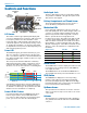
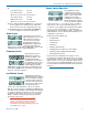
Power LED
The PWR LED glows green when the battery is good.
The color changes to red when there is about 30 min-
utes of operation left with the recommended lithium bat-
tery. When the LED begins to blink red, there are only a
few minutes of life.
The exact point at which the LED turns red will vary
with battery brand and condition, temperature and cur-
rent drain. The LED is intended to simply catch your
attention, not to be an exact indicator of remaining time.
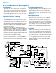
1.6
1.4
1.2
1.0
.8
2468
Hours
Voltage
Varies
Green Red Blink
A weak battery will sometimes cause the PWR LED to
glow green immediately after the transmitter is turned
on, but will soon discharge to the point where the LED
will turn red or the unit will turn off completely.
Power LED Off Feature
In normal operating mode, the DOWN and UP Arrow
buttons may be used to turn the PWR LED indica-
tors off and on. This setting does not persist through a
power cycle nor does it affect the LCD backlight.
Audio Input Jack
The Servo Bias input circuitry accommodates virtually
every lavaliere, handheld or shotgun microphone avail-
able, plus line level signals.
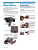
Battery Compartment and Thumb Screw
The large knurled thumbscrew is used to release or
secure the Battery Compartment Cover Plate.
Modulation LEDs
Proper input gain adjustment is critical to ensure the
best audio quality. Two bicolor LEDs will glow either red
or green to accurately indicate modulation levels. The
input circuitry includes a wide range DSP controlled
limiter to prevent distortion at high input levels.
It is important to set the gain (audio level) high enough
to achieve full modulation during louder peaks in the
audio. The limiter can handle over 30 dB of level above
full modulation, so with an optimum setting, the LEDs
will flash red during use. If the LEDs never flash red, the
gain is too low. In the table below, +0 dB indicates full
modulation.
Signal Level -20 LED -10 LED
Less than -20 dB Off Off
-20 dB to -10 dB Green Off
-10 dB to +0 dB Green Green
+0 dB to +10 dB Red Green
Greater than +10 db Red Red
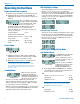
AUDIO Button
The AUDIO button is used to display the audio level and
low frequency roll-off settings. The UP and DOWN ar-
rows adjust the values.
The AUDIO button is also used with the FREQ button to
enter standby mode and to power the transmitter on or off.
FREQ Button
The FREQ Button displays the selected operating
frequency and toggles the LCD between displaying
the actual operating frequency in MHz and a two-digit
hexadecimal number that corresponds to the equivalent
Lectrosonics Frequency Switch Setting.
Up/Down Arrows
The Up and Down arrow buttons are used to select the
values on the various setup screens and to lock out the
control panel.
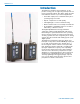
Antenna
The transmitter uses a whip antenna with a flexible wo-
ven, galvanized steel mesh cable and a standard SMA
connector.
Battery
Compartment
Thumb Screw
Battery
Compartment
Cover Plate
Audio
Input Jack
AUDIO Button FREQ Button
Modulation
LEDs
PWR LED
UP Arrow
DOWN Arrow
Antenna
Jack
LCD