INSTRUCTION MANUAL SM Super Miniature Belt-Pack Transmitter Including SMD, SMQ With Digital Hybrid Wireless™ Technology Fill in for your records: Serial Number: Purchase Date: Rio Rancho, NM, USA www.lectrosonics.
SM Thank you for selecting the Lectrosonics SM ultraminiature transmitter.
Super-Minature Belt Pack Transmitter Table of Contents General Technical Description .............................................................................................................................................................. 4 Introduction ........................................................................................................................................................................................... 4 Digital Hybrid Wireless™ Technology* .........................
SM General Technical Description Introduction The SM transmitter uses ±75 kHz wide deviation for an extremely high signal to noise ratio, switching power supplies to provide constant voltages to the transmitter circuits from the beginning (1.5 Volts) to the end (0.85 Volts) of battery life, and an ultra low noise input amplifier for quiet operation. It is gain protected with a wide range dual envelope input limiter which cleanly limits input signal peaks over 30 dB above full modulation.
Super-Minature Belt Pack Transmitter actual roll-off frequency will vary somewhat according to the low frequency response of the mic capsule being used. The low frequency roll-off is used to remove subsonic (or very low frequency) audio, often produced by air conditioning systems, automobile traffic and other sources from the audio signal. Excessive low frequency content in the audio input can cause a variety of audio problems including driving the transmitter into limiting.
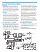
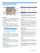
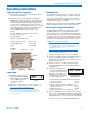
SM Controls and Functions Modulation LEDs Control Panel Battery Compartment Cover Plate LCD UP Arrow Antenna Battery Compartment Thumb Screw PWR LED Audio Input Jack AUDIO Button FREQ Button LCD Screen The LCD is a numeric-type Liquid Crystal Display used in conjunction with the AUDIO and FREQ buttons, and the UP and Down arrows, to configure the SM. (See SM SCREEN SELECTIONS.) It is also used with the Modulation and PWR LEDs to monitor system operation.
Super-Minature Belt Pack Transmitter SM Screen Selections Six screens are used to set up and operate the SM. These screens are used to set the operating frequency, adjust the audio modulation level, select the Compatibility Mode or lock the control panel and power down the transmitter. Audio Screen The Audio screen is the default screen at the end of the power up boot sequence. It can also be accessed by pressing the AUDIO button during normal operation.
SM Standby Mode Quickly pressing both the AUDIO and FREQ buttons from a power off condition places the unit in Standby Mode. In this Standby Screen mode, the screen displays “rf OFF” to inform the user that the unit is not transmitting. rF OFF Holding the FREQ button in Standby Mode displays the current operating frequency of the transmitter. The operating frequency can be changed by holding the FREQ button and pressing either the Up or Down button.
Super-Minature Belt Pack Transmitter Operating Instructions Power Up and Boot Sequence Standby Mode 1) Ensure that a good battery is installed in the unit. (See Battery Installation.) 2) Simultaneously press and hold the AUDIO and FREQ buttons until the Power On Boot Sequence is initiated. (See Power On Timer.) As the unit turns on, the Modulation LEDs and PWR LED all glow red, then green, and then they revert to normal operation, i.e.
SM Setting Transmitter Operating Frequency The Operating Frequency of the SM can be displayed either in MHz or as a two-digit hexadecimal number. (See Controls and Functions, FREQ Button.) The SM’s operating frequency can be set with the unit in Standby Mode or powered up for normal operation.
Super-Minature Belt Pack Transmitter Locking or Unlocking the Control Panel The Lock mode protects the transmitter from accidental changes to its settings. 1. Ensure the SM setup is complete (operating frequency, audio level, Compatibility Mode, sensitivity to remote control). 2. Simultaneously press both the Up and Down arrow buttons to start the Lock timer. When the timer Control Panel Locked reaches zero, “Loc” is displayed and the controls are locked.
SM 5-Pin Input Jack Wiring The wiring diagrams included in this section represent the basic wiring necessary for the most common types of microphones and other audio inputs. Some microphones may require extra jumpers or a slight variation on the diagrams shown. It’s virtually impossible to keep completely up to date on changes that other manufacturers make to their products. It is possible that you may encounter a microphone that differs from these instructions.
Super-Minature Belt Pack Transmitter Wiring Hookups for Different Sources In addition to the wiring hookups illustrated below, Lectrosonics makes a number of cables and adapters for other situations such as connecting musical instruments (guitars, bass guitars, etc.) to the transmitter. These cables can be found in our UHF or Accessories catalogs. Visit www.lectrosonics.com, or contact the factory for more information. he most radical change is that pin 4 is now a voltage selector pin.
SM Troubleshooting Before going through the following chart, be sure that you have a good battery in the transmitter. It is important that you follow these steps in the sequence listed. SYMPTOM TRANSMITTER PWR LED OFF POSSIBLE CAUSE 1) Battery is inserted backwards or dead. 2) Transmitter not powered up. (See Operating Instructions, Power UP and Boot Sequence.
Super-Minature Belt Pack Transmitter SYMPTOM HISS AND NOISE -- AUDIBLE DROPOUTS POSSIBLE CAUSE 1) Transmitter gain (audio level) far too low. 2) Receiver antenna missing or obstructed. 3) Transmitter antenna missing. 4) Operating range too great. 5) Signal interference. Turn off transmitter. If receiver’s signal strength indicator does not drop to nearly zero, this indicates an interferring signal may be the problem. Try a different operating frequency.
SM 16 LECTROSONICS, INC.
Super-Minature Belt Pack Transmitter Specifications and Features Operating frequencies: Block 21 537.600 - 563.100 Block 22 563.200 - 588.700 Block 23 588.800 - 607.900 and 614.100 - 614.300 Block 24 614.400 - 639.900 Block 25 640.000 - 665.500 Block 26 665.600 - 691.100 Block 27 691.200 - 716.700 Block 28 716.800 - 742.300 Block 29 742.400 - 767.900 Block 30 768.000 - 793.500 Block 31 793.600 - 819.100 Block 32 819.200 - 844.700 Block 33 844.800 - 865.000 Block 37 944.100 - 951.
SM 18 LECTROSONICS, INC.
Super-Minature Belt Pack Transmitter Service and Repair If your system malfunctions, you should attempt to correct or isolate the trouble before concluding that the equipment needs repair. Make sure you have followed the setup procedure and operating instructions. Check the interconnecting cables and then go through the TROUBLESHOOTING section in this manual.
LIMITED ONE YEAR WARRANTY The equipment is warranted for one year from date of purchase against defects in materials or workmanship provided it was purchased from an authorized dealer. This warranty does not cover equipment which has been abused or damaged by careless handling or shipping. This warranty does not apply to used or demonstrator equipment. Should any defect develop, Lectrosonics, Inc. will, at our option, repair or replace any defective parts without charge for either parts or labor.