
User's Manual
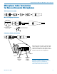

Digital Hybrid Wireless Belt-Pack Transmitters
Rio Rancho, NM
11
Format
Files
Format
Record
Gain
Formats the microSDHC memory
card.
WARNING: This function
erases any content on the
microSDHC memory card.
Record or Stop
Begins recording or stops recording. (See page 7.)
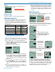
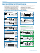
Adjusting the Input Gain
The two bicolor Modulation LEDs on the control panel
provide a visual indication of the audio signal level
entering the transmitter. The LEDs will glow either red
or green to indicate modulation levels as shown in the
following table.
Signal Level -20 LED -10 LED
Less than -20 dB
Off Off
-20 dB to -10 dB
Green Off
-10 dB to +0 dB
Green Green
+0 dB to +10 dB
Red Green
Greater than +10 dB
Red Red
NOTE: Full modulation is achieved at 0 dB, when
the “-20” LED first turns red. The limiter can cleanly
handle peaks up to 30 dB above this point.
It is best to go through the following procedure with the
transmitter in the standby mode so that no audio will en-
ter the sound system or recorder during adjustment.
1) With fresh batteries in the transmitter, power the unit
on in the standby mode (see previous section Turn-
ing Power ON and OFF).
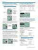
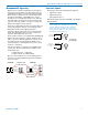
2) Navigate to the Gain setup screen.
Gain
Freq
Rolloff
Compat
-40
-20
0
Gain
25
3) Prepare the signal source. Position a microphone
the way it will be used in actual operation and have
the user speak or sing at the loudest level that will
occur during use, or set the output level of the in-
strument or audio device to the maximum level that
will be used.
4) Use the and arrow buttons to adjust the gain
until the –10 dB glows green and the –20 dB LED
starts to flicker red during the loudest peaks in the
audio.
5) Once the audio gain has been set, the signal can
be sent through the sound system for overall level
adjustments, monitor settings, etc.
6) If the audio output level of the receiver is too high or
low, use only the controls on the receiver to make
adjustments. Always leave the transmitter gain ad-
justment set according to these instructions, and do
not change it to adjust the audio output level of the
receiver.
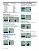
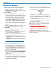
Selecting Frequency
The setup screen for frequency selection offers several
ways to browse the available frequencies.
Freq.
b 19
494.500
51
Gain
Freq
Rolloff
Compat
Press MENU/
SEL to select
one of four
fields to make
adjustments
Each field will step through the available frequencies in
a different increment. The increments are also different
in the 25 kHz mode from the 100 kHz mode.
Freq.
b 19
494.500
51
Freq.
b 19
494.500
51
These two fields step in 25 kHz
increments when the step size is 25
kHz and 100 kHz increments when
the step size is 100 kHz.
Freq.
b 19
494.500
51
Freq.
b 19
494.500
51
These two fields
always step in the
same increments
1 MHz steps
1 block steps
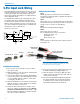
A fraction will appear next to the hex code in the setup
screen and in the main window when the frequency
ends in .025, .050 or .075 MHz.
474.525
-40
-20
0
b 470
1
4
51
Freq.
b 19
494.525
51
1
4
Fraction appears
next to hex code
in 25 kHz mode
All Lectrosonics Digital Hybrid Wireless
®
receivers
provide a scanning function to quickly and easily find
prospective frequencies with little or no RF interference.
In other cases, a frequency may be specified by officials
at a large event such as the Olympics or a major league
ball game. Once the frequency is determined, set the
transmitter to match the associated receiver.