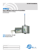
INSTRUCTION MANUAL SMDa Super Miniature Belt-Pack Transmitters With Digital Hybrid Wireless™ Technology US Patent 7,225,135 SMDa Dual battery, 100 mW RM/E Remote Control Fill in for your records: Serial Number: Purchase Date: Rio Rancho, NM, USA www.lectrosonics.
SMDa Series 2 LECTROSONICS, INC.
Super-Minature Belt Pack Transmitters Thank you for selecting a Lectrosonics SM Series ultra-miniature transmitter.
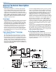
SMDa Series General Technical Description Wideband Design Digital Hybrid transmitters use ±50 kHz wide deviation for an excellent signal to noise ratio and wide dynamic range. The DSP controlled input limiter features a wide range dual envelope design which cleanly limits input signal peaks over 30 dB above full modulation. Switching power supplies to provide constant voltages to the trans mitter circuits from the beginning (1.5 Volts) to the end (0.
Super-Minature Belt Pack Transmitters Low Frequency Roll-Off The low frequency roll-off can be set for a 3 dB down point at 35, 50, 70, 100, 120 and 150 Hz to control sub sonic and very low frequency audio content in the au dio. The actual roll-off frequency will vary slightly depend ing upon the low frequency response of the microphone. Excessive low frequency content can drive the transmit ter into limiting, or in the case of high level sound sys tems, can even cause damage to loudspeaker systems.
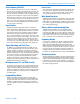
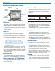
SMDa Series Controls and Functions Modulation LEDs Battery Compartment Cover Plate Modulation LEDs LCD UP Arrow Audio Input Jack Battery Compartment Thumb Screw PWR LED DOWN Arrow AUDIO Button FREQ Button LCD Screen The LCD is a numeric-type Liquid Crystal Display with several screens that allow settings to be made with the AUDIO, FREQ, UP and DOWN to configure the trans mitter.
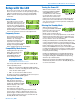
Super-Minature Belt Pack Transmitters Setup with the LCD Six screens are used to set up and operate the SM. These screens are used to set the operating frequency, adjust the audio input level, select the Compatibility Mode or lock the control panel and power down the transmitter. Audio Screen The Audio screen is used to adjust input gain from 0 to +44 dB, and the low frequency rolloff from 35 to 150 Hz. Repeat edly pressing the AUDIO button toggles back and forth between the two displays.
SMDa Series Lock/Unlock Screen Simultaneously pressing and holding both the Up and Down arrow buttons during normal operation starts the Lock timer. The timer starts at three and counts down to zero. When the timer reaches zero, the transmit ter’s controls are locked. The LCD will display the locked condition as long as the arrow buttons are held, then revert back to the previous screen when either button is released.
Super-Minature Belt Pack Transmitters Operating Instructions Power Up and Boot Sequence Standby Mode 1) Ensure that good batteries are installed in the unit. (See Battery Installation.) 2) Simultaneously press and hold the AUDIO and FREQ buttons until the Power On Boot Sequence is initiated. (See Power On Timer.) As the unit turns on, the Modulation LEDs and PWR LED all glow red, then green, and then they revert to normal opera tion, i.e.
SMDa Series Setting Transmitter Operating Frequency Attaching a Microphone and Adjusting Gain Frequency displayed in MHz The Operating Frequency of the SMDa can be displayed either in MHz or as a two-digit hexa decimal number. (See Controls and Functions, FREQ Button.) Frequency displayed as The SM’s operating frequency two-digit hexadecimal can be set with the unit in number Standby Mode or powered up for normal operation.
Super-Minature Belt Pack Transmitters Locking or Unlocking the Control Panel Control Panel Locked 2 The Lock mode protects the transmitter from accidental changes to its settings. 1) Ensure the SMDa setup is complete (operating fre quency, audio level, Compatibility Mode, sensitivity to remote control). 2) Simultaneously press both the Up and Down ar row buttons to start the Lock timer. When the timer reaches zero, “Loc” is displayed and the controls are locked.
SMDa Series 5-Pin Input Jack Wiring The wiring diagrams included in this section represent the basic wiring necessary for the most common types of microphones and other audio inputs. Some micro phones may require extra jumpers or a slight variation on the diagrams shown. Audio input jack wiring: It is virtually impossible to keep completely up to date on changes that other manufacturers make to their products, thus you may encounter a microphone that differs from these instructions.
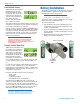
Super-Minature Belt Pack Transmitters Microphone Cable Termination for Non-Lectrosonics Microphones TA5F Connector Assembly Mic Cord Stripping Instructions 1 4 5 2 3 VIEW FROM SOLDER SIDE OF PINS 0.15" 0.3" Crimping to Shield and Insulation Strip and position the cable so that the clamp can be crimped to contact both the mic cable shield and the insulation. The shield contact reduces noise with some microphones and the insulation clamp increases ruggedness.
SMDa Series Microphone RF Bypassing When used on a wireless transmitter, the microphone element is in the proximity of the RF coming from the transmitter. The nature of electret microphones makes them sensitive to RF, which can cause problems with the microphone/transmitter compatibility. If the electret microphone is not designed properly for use with wire less transmitters, it may be necessary to install a chip capacitor in the mic capsule or connector to block the RF from entering the electret capsule.
Super-Minature Belt Pack Transmitters Wiring Hookups for Different Sources In addition to the microphone and line level wiring hookups illustrated below, Lectrosonics makes a number of cables and adapters for other situations such as con necting musical instruments (guitars, bass guitars, etc.) to the transmitter. Visit www.lectrosonics.com and click on Accessories, or download the master catalog.
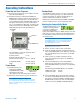
SMDa Series RM Remote Control Operating Instructions RM Front Panel Controls A single AA Lithium battery will operate the RM for up to several years. The RM unit gives you remote control of SM Series transmitters using an audible tone delivered to the transmitter’s microphone. Operating parameters on the transmitter can be set by holding the speaker on the RM close to the microphone and pressing the pushbut ton.
Super-Minature Belt Pack Transmitters Operating Notes • The sensitivity to the remote control varies with the trans mitter’s audio level setting and the microphone used, but it is always possible to make it work with a sufficiently loud remote signal at close range. • If the SMa is configured to respond to the remote con trol, it will do so even if the buttons are locked. • When the SMa is asleep, it can only be awakened by the remote control, or by remov ing and reinserting the bat tery.
SMDa Series Troubleshooting Before going through the following chart, be sure that you have a good battery in the transmitter. It is important that you follow these steps in the sequence listed. SYMPTOM POSSIBLE CAUSE TRANSMITTER PWR LED OFF 1) 2) AUDIO LEVEL LEDs NOT LIGHTING 1) 2) 3) 4) RECEIVER RF INDICATOR OFF 1) 2) 3) 4) Battery is inserted backwards or dead. Transmitter not powered up. (See Operating Instructions, Power UP and Boot Sequence.
Super-Minature Belt Pack Transmitters SYMPTOM POSSIBLE CAUSE HISS AND NOISE -- AUDIBLE DROPOUTS 1) 2) 3) 4) 5) Transmitter gain (audio level) far too low. Receiver antenna missing or obstructed. Transmitter antenna broken or missing. Operating range too great. Signal interference. Turn off transmitter. If receiver’s signal strength indicator does not drop to nearly zero, this indicates an interfering signal may be the problem. Try a different operating frequency.
SMDa Series Included Accessories SMDa: PSMD Leather pouch with integrated belt clip 35924 SMDBCSL Themal insulated pad installed on SMDa Spring-loaded machined aluminum clip Place Thermal insulation pad on back of unit, as pictured. Optional Accessories SMKITTA5 20 Connector kit for SMa series transmitters, 5-pin TA5F plug with sleeve SMDBC Machined, wire belt clip for SMDa and transmitters LECTROSONICS, INC.
Super-Minature Belt Pack Transmitters Specifications and Features Operating frequencies: Block 470 470.100 - 495.600 Block 19 486.400 - 511.900 Block 20 512.000 - 537.500 Block 21 537.600 - 563.100 Block 22 563.200 - 588.700 Block 23 588.800 - 607.900 and 614.100 - 614.300 Block 24 614.400 - 639.900 Block 25 640.000 - 665.500 Block 26 665.600 - 691.100 Block 27 691.200 - 716.700 Block 28 716.800 - 742.300 Block 29 742.400 - 767.
SMDa Series Service and Repair If your system malfunctions, you should attempt to correct or isolate the trouble before concluding that the equipment needs repair. Make sure you have followed the setup procedure and operating instructions. Check the interconnecting cables and then go through the Troubleshooting section in this manual. We strongly recommend that you do not try to repair the equipment yourself and do not have the local repair shop at tempt anything other than the simplest repair.
Super-Minature Belt Pack Transmitters Rio Rancho, NM 23
LIMITED ONE YEAR WARRANTY The equipment is warranted for one year from date of purchase against defects in materials or workmanship provided it was purchased from an authorized dealer. This warranty does not cover equipment which has been abused or damaged by careless handling or shipping. This warranty does not apply to used or demonstrator equipment. Should any defect develop, Lectrosonics, Inc. will, at our option, repair or replace any defective parts without charge for either parts or labor.