
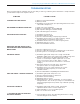
User's Manual


13
Frequency Agile UHF Ultra-Miniature Belt-Pack Transmitter
Rio Rancho, NM – USA
electret microphones provided the microphone
has its own built-in battery.
PIN 4 Bias voltage selector for Pin 3. Pin 3 voltage (0,
2 or 4 volts) depends on Pin 4 connection.
Pin 4 tied to Pin 1: 0 V
Pin 4 Open: 2 V
Pin 4 to Pin 2: 4 V
PIN 5 High impedance, line level input for tape decks,
mixer outputs, musical instruments, etc.
MICROPHONE RF BYPASSING
Some mics require RF protection to keep the radio signal
from affecting the capsule, even though the transmitter
input circuitry is already RF bypassed (see schematic
diagram).
If the mic is wired as directed, and you are having
difficulty with squealing, high noise, or poor frequency
response; RF is likely to be the cause.
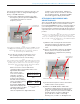
The best RF protection is accomplished by installing RF
bypass capacitors at the mic capsule. If this is not
possible, or if you are still having problems, capacitors
can be installed on the mic pins inside the TA5F connec-
tor housing.
Install the capacitors as follows: Use 330 pF capacitors.
Capacitors are available from Lectrosonics. Please
specify the part number for the desired lead style.
Leaded capacitors: P/N 15117
Leadless capacitors: P/N SCC330P
All Lectrosonics lavaliere mics are already bypassed and
do not need any additional capacitors installed for proper
operation.
LINE LEVEL SIGNALS
The normal hookup for line level signals is: Signal Hot
to pin 5, Signal Gnd to pin 1 and pin 4 jumped to pin 1.
This allows signal levels up to 3V RMS to be applied
without limiting.
The wiring diagrams included in this section represent
the basic wiring necessary for the most common types
of microphones and other audio inputs. Some micro-
phones may require extra jumpers or a slight variation
on the diagrams shown.
It’s virtually impossible to keep completely up to date on
changes that other manufacturers make to their prod-
ucts. It is possible that you may encounter a microphone
that differs from these instructions. If this occurs please
call our toll-free number listed under Service and Repair
in this manual or visit our web site at:
http://www.lectrosonics.com
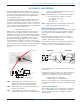
When used on a wireless transmitter, the microphone
element is in the proximity of the RF coming from the
transmitter. The nature of electret microphones makes
them sensitive to RF, which can cause problems with the
microphone/transmitter compatibility. If the electret
microphone is not designed properly for use with wire-
less transmitters, it may be necessary to install a chip
capacitor in the mic capsule or connector to block the RF
from entering the electret capsule. (See
RF Bypassing
.)
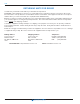
The Audio Input Jack for the SM is wired as shown
below:
PIN 1 Shield (ground) for positive biased electret
lavaliere microphones. Shield (ground) for
dynamic microphones and line level inputs.
PIN 2 Bias voltage source for positive biased electret
lavaliere microphones.
PIN 3 Low impedance microphone level input for
dynamic microphones. Also accepts hand-held
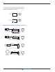
5-PIN INPUT JACK WIRING
3 WIRE MIC2 WIRE MIC
CAPSULE
CAPSULE
SHIELD
AUDIO
SHIELD
AUDIO
BIAS
Alternate locations for bypass capacitors
TA 5F
CONNECTOR
TA 5F
CONNECTOR
Preferred locations for bypass capacitors
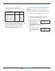
SM Equivalent Input Circuit Wiring
10k
1k
5
4
3
2
1
To Virtual Ground
Audio Amplifier
BIAS
MIC
SOURCE LOAD
LINE IN
GND
+
30uF
+6 VDC
Servo Bias
Pin 4 to Pin 1 = 0 V
Pin 4 Open = 2 V
Pin 4 to Pin 2 = 4 V
+
To Limiter Control
30uF
750 Ohm
100 Ohm
2.7K
200 Ohm
+
3.3uF
Audio Input Jack