INSTRUCTION MANUAL LE Series Wireless Microphone System Fill in for your records: Serial Number: Purchase Date: Rio Rancho, NM, USA www.lectrosonics.
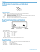
LE Series R176 Receiver Connections and Indicators Front Panel Front Panel Indicators Modulation: 0 dB: -20 dB: Inidcates the modluation level of the output from the associated transmitter Flickers when the transmitter gain approaches 0 dB Flickers when the transmitter gain approaches -20 dB. Glows continuously when the output from the transmitter is above -20 dB.
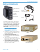
Wireless Microphone System Audio Level Adjustments Battery Indicator Lamp Power ON/OFF Switch M119RLM with threaded locking connector MIC LEVEL Adjustment Microphone Jack M119RA The M175DC transmitter features a wide range input limiter to guard against overload distortion and allow maximum signal to noise ratio. The following procedure will adjust the wireless system to take full advantage of the limiter action to prevent excessive output level from the receiver from overloading the recorder.
Service and Repair If your system malfunctions, you should attempt to correct or isolate the trouble before concluding that the equipment needs repair. Make sure you have followed the setup procedure and operating instructions. Check the interconnecting cables. We strongly recommend that you do not try to repair the equipment yourself and do not have the local repair shop attempt anything other than the simplest repair.