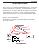
R175 Compact Receiver OPERATING INSTRUCTIONS and trouble-shooting guide Digital Code Squelch LECTROSONICS, INC.
INTRODUCTION The R175 is a fixed frequency, crystal controlled receiver designed for use in public address applications. A proprietary Digital Code Squelch* is used in the system design to eliminate squelching problems caused by interference. The compact size of the receiver permits mounting the receiver almost anywhere. The audio output is a balanced XLR type, variable in level, to match any type of sound system.
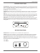
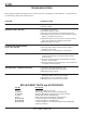
Compact Receiver RECEIVER FRONT PANEL -20 and 0dB LEDs - Indicates the modulation (audio level) of the incoming signal - see transmitter manual for proper adjustment of transmitter “MIC LEVEL” or “GAIN.” The -20 lamp should flicker, or stay lit as you speak into the micro phone. The 0dB lamp is a “peak” indicator showing that the audio level in the transmitter is being limited. It is normal to see an occasional flicker of the 0dB lamp. OFF-ON Switch - This slide switch turns the power off and on.
SYSTEM SETUP AND OPERATION 1) Connect the supplied CH-12 to the power jack on the rear panel. 2) Attach the antenna. 3) Connect the audio cable. XLR Output: Pin 1 - ground Pin 2 - audio (+) Pin 3 - audio (-) 4) Set front panel switch to “ON.” Check to see that the red POWER LED lights up. 5) Adjust transmitter “GAIN.” This is perhaps the most important step in the set up procedure.
Compact Receiver ANTENNA USE AND PLACEMENT Connect the antenna to the rear panel jack. Extend the antenna fully if you are using a telescoping type. Position the antenna so that it is not touching or within 3 or 4 feet of large metal surfaces. It is also good practice to position the receiver so that there is a direct “line of sight” between the transmitter and the receiver antenna. If the antenna needs to placed away from the receiver, use a proper external antenna.
TROUBLESHOOTING Before going through the following chart, be sure that you have a good battery in the transmitter. It is important that you follow these steps in the sequence listed. SYMPTOM POSSIBLE CAUSE TRANSMITTER BATTERY LED OFF 1) Battery is inserted backwards. 2) Battery is dead. RECEIVER CODE LAMP OFF 1) Transmitter not turned on. 2) Transmitter battery is dead. 3) Receiver antenna missing or improperly positioned. 4) Transmitter and receiver not on same frequency.
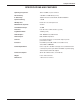
Compact Receiver SPECIFICATIONS AND FEATURES Operating Frequencies: 169 to 198 MHz, crystal controlled RF Sensitivity: -110 dBm for 20 dB Sinad (0.7 uV) IF Selectivity: 150 kHz interference bandwidth; -30 dB @ ±200 kHz Squelch Quieting: -109 dB AM Rejection: Below the noise at all input levels Modulation Acceptance: ±15 kHz Third Order Intercept: +5 dBM Distortion: 0.5% @ 1 kHz, 12 kHz deviation (system) Signal/Noise Ratio: -90 dB (system) Audio Outputs: XLR: 200 Ohms bal; 100 mV max.
SERVICE AND REPAIR If your system malfunctions, you should attempt to correct or isolate the trouble before concluding that the equipment needs repair. Make sure you have followed the setup procedure and operating instructions. Check out the intercon necting cords and then go through the TROUBLE SHOOTING section in the manual We strongly recommend that you do not try to repair the equipment yourself and do not have the local repair shop attempt anything other than the simplest repair.
Compact Receiver This page intentionally blank.
LIMITEDONE ONE YEAR LIMITED YEARWARRANTY WARRANTY The equipment is warranted for one year from date of purchase against defects in materials or workmanship provided it was purchased from an authorized dealer. This warranty does not cover equipment which has been abused or damaged by careless handling or shipping. This warranty does not apply to used or demonstrator equipment. Should any defect develop, Lectrosonics, Inc.