QUADUHFD MULTI-CHANNEL WIRELESS SYSTEM WITH RF/POWER DISTRIBUTION OPERATING INSTRUCTIONS and trouble-shooting guide LECTROSONICS, INC. Rio Rancho, NM USA www.lectrosonics.
INTRODUCTION The design of Lectrosonics Quad Pak systems has evolved over the years as a result of suggestions garnered during many conversations with industry sound mixers and production engineers. These suggestions, together with meticulous attention to design and construction details, have resulted in a system that offers portability, versatility, and “bullet-proof” reliability of operation.
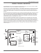
Multi-channel Wireless System GENERAL TECHNICAL DESCRIPTION The QUADUHFD consists of three sub-systems; the housing which contains the gel-cell power supply, the UDM6 RF/power distribution module and the UDM6S RF distribution module. The housing is constructed of machined aluminum. A strap handle is bolted directly to the top panel of the housing for ease of carrying. The lead-acid gel-cell batteries are connected in series to provide 12 VDC (nominal) power to all the modules installed into the system.
FRONT PANEL DESCRIPTION ANTENNA LEADS - These BNC terminated leads provide isolated RF signals for each receiver installed in the system. ANTENNA - The antenna provided with the unit attaches to this BNC connector directly with a twist lock motion. Other 50 Ohm antennas may also be used.
Multi-channel Wireless System REAR PANEL DESCRIPTION SERIAL/FREQUENCY LABEL - This label, located on the rear of the housing on each distribution module, indicates the serial number and the RF passband of the distribution module. IMPORTANT - The receivers installed in the unit must fall between the passband indicated on the label. Serious signal loss results if the receiver frequencies are outside the RF passband.
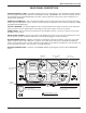
RECEIVER INSTALLATION The QUADUHFD is designed to contain up to four receivers. Installation of these receivers is quite simple. First, loosen but do not remove, the two large counter-sunk phillips head screws in the front panel and the two in the rear panel of the housing. (See drawings on previous pages) Insert the receivers, front end first (the end with the an tenna connection), in through the rear panel. Seat the front end of the receiver into the recessed lip of the front panel.
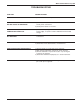
Multi-channel Wireless System TROUBLESHOOTING SYMPTOM POSSIBLE CAUSE NO POWER LEDs OR AUDIO 1) Power switch in the OFF position. Switch to EXT or EXT OR BAT. POWER LED LIGHTS ON UDM6 BUT NO LIGHTS ON RECEIVERS 1) Power leads in back not connected to receivers. Check power connections. 2) Check power switch on receivers. NO POWER LEDs, ALL CONNECTIONS CHECK OK 1) Gel-cell battery charge too low. Either use an external 12 VDC power supply, or operate on110 to 240 VAC with the CH-80 charger.
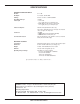
SPECIFICATIONS RF/POWER DISTRIBUTION MODULE RF Gain: 0 to +1 dB RF Output: Filtering: Third Order Intercept: Power Input: Four outputs, 50 Ohm, BNC Ceramic resonators - 50MHz bandwidth +27 dBm • 9 to 16 V DC Pins 1 (gnd) and 4 (+) on XLR power jack • CH-80 adapter for AC operation, 15V @ 2.8 A Pins 2 (gnd) and 3 (+) on XLR power jack Power Consumption: 200 mA at 14V (distribution modules only) Total draw is dependent on the receiver types involved and can be as high as two amps total.
Multi-channel Wireless System SERVICE AND REPAIR If your system malfunctions, you should attempt to correct or isolate the trouble before concluding that the equipment needs repair. Make sure you have followed the setup procedure and operating instructions.
LIMITEDONE ONE YEAR WARRANTY LIMITED YEAR WARRANTY The equipment is warranted for one year from date of purchase against defects in materials or workmanship provided it was purchased from an authorized dealer. This warranty does not cover equipment which has been abused or damaged by careless handling or shipping. This warranty does not apply to used or demonstrator equipment. Should any defect develop, Lectrosonics, Inc.