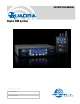
INSTRUCTION MANUAL TM Digital IEM System Fill in for your records: Serial Number: Purchase Date: Rio Rancho, NM, USA www.lectrosonics.
QUADRA 2 LECTROSONICS, INC.
Digital IEM System Table of Contents FCC Notice ............................................................................... 4 Industry Canada Notices ........................................................ 4 Safety Notes............................................................................. 4 System Overview..................................................................... 5 Receiver Transmitter Receiver Operation..................................................................
QUADRA FCC Notice NOTE: This equipment has been tested and found to comply with the limits for a Class B digital device, pursuant to Part 15 of the FCC Rules. These limits are designed to provide reasonable protection against harmful interference in a residential installation. The equipment generates, uses and can radiate radio frequency energy and, if not installed and used in accordance with the instructions, may cause harmful interference to radio communications.
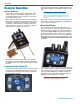
Digital IEM System System Overview The Quadra system provides an entirely new level of audio and RF performance in a wireless monitor system. The combination of analog or digital input capability, ultra-low latency 24 bit, 48 kHz audio, digital RF modulation and discrete four channel mixing capa bility make the Quadra a truly unique IEM product for mission-critical, professional applications. The system is designed for line level analog audio signals and AES/EBU digital audio input signals.
QUADRA Receiver Operation Battery Insertion The receiver is powered by three AA batteries, either alkaline, lithium, or rechargeable types. Do not use “heavy duty” batteries from a drug store - they will not last long in the M4 receiver. Open the battery door by pressing on it while sliding it downward. It should then flip open allowing full access to the battery compartment. Carefully note the battery orientation as indicated by the diagrams inside.
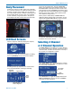
Digital IEM System Body Placement Position the receiver on a belt, guitar strap, wardrobe, etc. so that the antennas are oriented vertically and not touching a metallic surface. Make sure the antennas are on the outside of thick or metallic costuming so the antenna whips will be out in the open. For maximum receive sensitivity, it is good practice to keep the an tenna whips from direct contact with a person’s body.
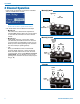
QUADRA 2 Channel Operation In this mode, two channels are fed to the transmitter and are available at the receiver. Master(1,2) mode AUDIO CH. 1 2 MASTER VOLUME NOTE: the transmitter must be also in 2 Channel mode for the receiver to operate in this manner. 2-ch. mode allows for three different knob setups: • Master(1,2) This is the factory default and is equivalent to standard IEM systems where only a stereo signal is used. The tall, thin knob is the stereo master volume.
Digital IEM System 4 Channel Operation In this mode, all four audio channels fed to the trans mitter are available at the receiver. Master(1,2)+3,4 mode AUDIO CH. 1 2 AUDIO AUDIO CH. 3 CH. 4 MASTER VOLUME NOTE: the transmitter must be in 4 Channel mode for the receiver to work in this manner.
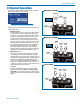
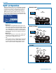
QUADRA Split 1,2 Operation Split modes allow you to use a single M4T transmitter running in the 4 Channel mode to send two different 2 channel stereo mixes to two different receivers or groups of receivers using a single radio frequency. Split 1+2 mode delivers audio channels 1 and 2 to the tall, thin knob and the lower concentric knob. The knobs can be set up to function in three different ways. Master(1,2) mode AUDIO CH.
Digital IEM System Split 3,4 Operation Split modes allow you to use a single M4T transmitter running in the 4 Channel mode to send two different 2 channel stereo mixes to two different receivers or groups of receivers using a single radio frequency. Split 3+4 mode delivers audio channels 3 and 4 to the tall, thin knob and the lower concentric knob. The knobs can be set up to function in three different ways. Master(3,4) mode AUDIO CH.
QUADRA Single Channel Operation The Single mode allows you to use one M4T transmit ter running in the 4 Channel mode to send up to four mono mixes to up to four different receivers or groups of receivers using a one radio frequency. This delivers the selected audio channel to the tall, thin knob as the master volume. Any one of the four audio channels sent to the transmitter can be routed to the master knob. The other three knobs have no function. M(2) MASTER VOLUME AUDIO CH.
Digital IEM System Additional Setup Options Pan Tune To select your RF operating frequency, choose Tune in the menu list, and press the MENU/SEL button. Here, you can choose between four operating frequen cies in the 4 Channel mode or one of the Split modes, or eight operating frequencies the in 2 Channel mode. To select your overall stereo balance and stereo pan ning for individual audio channels, use the arrow but tons to highlight Pan in the menu list.
QUADRA Limiter Treble Shelf This feature can be used in order to provide audio lim iting at the receiver in order to prevent excessive levels at the headphones or earbuds. To set the amount of limiting, highlight “Limiter” in the menu list using the ar row keys. Press MENU/SEL to choose this function. Use the arrow keys to select the limiter threshold in 3 dB increments. Test it with a known signal to deter mine the maximum sound level you are comfortable with.
Digital IEM System Factory Defaults This is used if you intend to reset the receiver back to factory settings. Select Defaults on the main menu and press MENU/SEL to select the two choices. Using the Presets Presets can be used to store all user settings includ ing Channel Setup, knob configuration, panning, and operating frequency. Five factory presets give you the most common starting configurations, while eight user presets allow you to customize your receiver and store those detailed settings.
QUADRA The first five presets, A - E, are permanently loaded with the most common channel setup and knob con figuration combinations: Factory A: 4-channel, M(1,2)+3+4 (see p. 9) Factory B: 4-channel, M(1)+2+3+4 (see p. 9) Factory C: 2-channel, M(1,2) (see p. 8) Factory D: split 1, 2, M(1,2) (see p. 10) Factory E: split 3, 4, M(3,4) (see p. 11) Factory presets can be modified by changing the knob setup, panning or any other parameter and then saved as a user preset for later recall.
Digital IEM System Accessories P/N 25984 replacement wire belt clip. BCHINGED Spring-loaded belt clip kit P/N 35747 rubber cushion CCM4R Foam lined carrying case.
QUADRA Transmitter Front Panel DIGITAL IEM TM Headphone Monitor Channel Select Buttons Power Switch Transmitter Rear Panel Antenna Output ANT Analog Audio Inputs 4 3 1 2 USB 100-240 VAC, 50/60 Hz, 5W Power Inlet 100-240 VAC, 50/60 Hz, 5 W 18 S/N DIGITAL IEM TRANSMITTER USB Port for Firmware Updates AES IN CH3/CH4 AES IN CH1/CH2 Digital Audio Inputs LECTROSONICS, INC.
Digital IEM System Initial Setup Connect AC power to the M4T transmitter using the provided power cable. To ensure that the power cable can not come loose, use the provided wire retainer. LCD The Main Window shows the following: • Operating frequency Frq1, Frq2, etc. for 4 channel or Split operation Frq1a, Frq1b, Frq2a, etc.
QUADRA Transmitter Menus To access the setup menus, press the MENU/SEL but ton at the upper left of the membrane panel. To back up one level or return to the Main Window, press the BACK button. The arrow keys along the right side of the control panel allow you to navigate between menu options and to adjust specific parameters within the menu windows. Tuning Once you have selected a channel setup, you can choose an RF operating frequency.
Digital IEM System Audio Trim Lock Setup When using analog inputs, this feature gives you the opportunity to adjust the transmitter input gain in 1 dB increments, on a per-channel basis. For very “hot” analog signals from the console, you may need to attenuate the input gain to compensate, thus avoiding clipping and the resulting signal distortion. To select audio input trim levels, use the UP/DOWN arrow buttons to highlight Audio Trim, then use the MENU/SEL button to enter this page.
QUADRA Rack Mount Hardware The M4T is delivered with a partial set of rack mount hardware, including bolts, a rack ear, connecting flanges, antenna cable and front-panel handles. With two M4T units, there is enough hardware supplied to connect the two units together, front-mount the anten nas, and prepare the units as a complete assembly ready for mounting in a rack enclosure. 3. Insert the adapter plate (the one with threaded nuts) into the slot behind the front panel.
Digital IEM System 7. Attach the antenna wires to the antenna ports on the back of the transmitters. 8. Attach the supplied antenna cable protectors to the sides of the transmitters right behind the rack ears. Secure them with the supplied screws. Note: This part will fit tightly and is meant to deform slightly during installation t maintain pressure on the coaxial connector. The dual set of M4T transmitters is now ready for rack mounting.
QUADRA Single Unit Rack-Mount Instructions Optional RMPM4T-1 Kit This kit is required to rack mount a single transmitter. 4. Attach front bracket plate to right side of panel. Insert the screws partially, but do not tighten them yet. 5. Attach the blank panel to the bracket and tighten all four screws. Assembling the optional RMPM4T-1 kit: 1. Remove the plastic end-caps from the front of the M4T transmitter.
Digital IEM System 9. Attach the supplied antenna and antenna connec tor guard. Note that this item will fit tightly and is meant to deform slightly during installation. The finished assembly will position the transmitter in the rack as shown here. In this example, the antenna loop through is not being used.
QUADRA Replacement Parts P/N 25989 rack ear flange Antenna cable kit P/N 25996 connector guard P/N 14247 rack handle P/N 21808 coaxial cable P/N 28600 screw; SEMS 4-40x1/4 Phillips Front and Rear mounting brackets P/N 25991 front P/N 35702 hex key (allen wrench) P/N 25990 rear P/N 21499 power cord, 6 ft.
Digital IEM System Firmware Updates As new versions of the firmware become available, updates are accomplished with a software utility and simple procedure. In many cases, updates must be made to both transmitter and receiver to ensure com patibility and provide the latest feature set. The software interface operates with Windows 2000, XP, Vista and Windows 7 operating systems. Configuring the USB Port 1) Remove any previous LecNet2 installation from your computer. 2) Install LecNet2 software.
QUADRA Troubleshooting Guide Symptom Cause Action Transmitter and receiver on, receiver shows strong RF signal, but no blue RF LED on receiver and no audio Transmitter and receiver are not both using the same channel setup Decide which channel setup (2-channel, 4-channel, or split modes) you plan to use and set both the transmitter and receiver the same. Remember that for split modes to work on the receiver, the transmitter must be set to 4-channel mode.
Digital IEM System Service and Repair If your system malfunctions, you should attempt to correct or isolate the trouble before concluding that the equip ment needs repair. Make sure you have followed the setup procedure and operating instructions. Check the inter connecting cables and then go through the Troubleshooting section in this manual. We strongly recommend that you do not try to repair the equipment yourself and do not have the local repair shop attempt anything other than the simplest repair.
QUADRA Specifications Overall System Operating Spectrum: Center Frequencies (MHz): 4-channel Mode: Center Frequencies: (MHz): 2-channel Mode: Modulation Type: Occupied Bandwidth: Audio Sampling: Latency (overall system): Digital Source: Analog Source: Selectable Audio Inputs: Audio Performance (overall system): Frequency Response: THD+N: Dynamic Range: Adjacent Channel Isolation: 902 - 928 MHz 907.776, 912.384, 916.992, 923.
Digital IEM System Rio Rancho, NM 31
LIMITED ONE YEAR WARRANTY The equipment is warranted for one year from date of purchase against defects in materials or workmanship provided it was purchased from an authorized dealer. This warranty does not cover equipment which has been abused or damaged by careless handling or shipping. This warranty does not apply to used or demonstrator equipment. Should any defect develop, Lectrosonics, Inc. will, at our option, repair or replace any defective parts without charge for either parts or labor.