PRO 4 MINI MULTI CHANNEL WIRELESS SYSTEM WITH CDM4 DISTRIBUTION MODULE OPERATING INSTRUCTIONS and trouble-shooting guide LECTROSONICS, INC.
INTRODUCTION The PRO 4 mini system is a high quality wireless microphone system designed primarily for motion picture and television production - both in the studio and in the field. The design features included are the direct result of suggestions garnered during many conversations with industry engineers, cameramen, and audio producers.
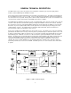
GENERAL TECHNICAL DESCRIPTION The PRO 4 mini consists of two sub-systems; the housing which contains the gel-cell power supply and the modules, and the CDM4 RF/power distribution module. The housing is built of machined aluminum and covered with a vinyl carrying case. The handle is bolted directly to the top aluminum panel of the case for security. The 6V, 4.8 Ah Panasonic LCR-456-P lead-acid gel-cell batteries are connected in series to provide 12 Vdc power to all the modules installed into the system.
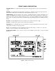
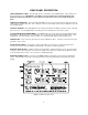
FRONT PANEL DESCRIPTION ANTENNA LEADS - These BNC terminated leads provide isolated RF signals for each receiver installed in the system. ANTENNA - The helical antenna provided with the unit attaches to this BNC connector directly with a twist lock motion. Other 50 Ohm antennas designed for the VHF high band may also be used. POWER SWITCH - The power switch has three positions. The OFF position turns off power to all modules in the system.
REAR PANEL DESCRIPTION SERIAL/FREQUENCY LABEL - This label indicates the serial number of the CDM4 module. It also indicates the RF pass-band of the unit. IMPORTANT - The CR185 receivers installed in the unit must fall between the frequencies indicated on the label. Serious signal loss results if the receivers are outside the RF passband. POWER XLR CONNECTOR - This 4 pin Switchcraft D4M connector is the power input jack for both the CH-50 AC charger and for external 12V power.
INSTALLATION The CDM4 RF/power distribution module is permanently installed into the housing assembly and should never need to be removed except in the rare case of repair. Removal of the CDM4 module requires case disassembly and is not recommended. The PRO4 mini is designed to contain up to four CR185 receivers. Installation of these receivers is quite simple. First, loosen but do not remove the two large counter-sunk phillips head screws in the front and two in the rear panels of the housing.
TROUBLESHOOTING SYMPTOM POSSIBLE CAUSE NO POWER LEDs OR AUDIO 1) Power switch in the OFF position. Switch to MAIN/EXT. POWER LED LIGHTS ON CDM4 BUT NO LIGHTS ON CR185’s 1) Power leads in back not connected to receivers. Check power connections. NO POWER LEDs, ALL CONNECTIONS CHECK OK 1) Gel-cell battery charge too low. Either switch to INT 9V setting on CDM4, use an external 12 Vdc power supply, or operate on 110 Vac with the CH-50 charger.
SPECIFICATIONS CDM4 RF/POWER DISTRIBUTION MODULE RF Gain: 1.
SERVICE AND REPAIR If your system malfunctions, you should attempt to correct or isolate the trouble before concluding that the equipment needs repair. Make sure you have followed the setup procedure and operating instructions. Check out the inter-connecting cords and then go through the TROUBLE SHOOTING section in the manual We strongly recommend that you do not try to repair the equipment yourself and do not have the local repair shop attempt anything other than the simplest repair.
LIMITED ONE YEAR WARRANTY The equipment is warranted for one year from date of purchase against defects in materials or workmanship provided it was purchased from an authorized dealer. This warranty does not cover equipment which has been abused or damaged by careless handling or shipping. This warranty does not apply to used or demonstrator equipment. Should any defect develop, we will, at our option, repair or replace any defective parts without charge for either parts or labor.