
Manual


PA8
4
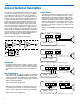
The PA8 uses a straightforward, low parts count design
for long term reliability. The heart of the power supply is
a low radiation toroidal transformer. The toroidal trans-
former generates less heat than a comparable non-toroi-
dal type, and emits considerably less 60Hz energy. This
is particularly important when the PA8 is used in close
proximity to microphone preamplifiers. The input to the
PA8 is fully balanced and RF filtered. The level control
feeds a monolithic power amplifier. Each power ampli-
fier is internally power limited to protect itself from short
circuits, excessively low impedances, or highly reactive
loads. Thermal limiting is also integrated into the power
amplifier, with an intelligent shutdown mode that minimiz-
es thermal shock to the device under extreme operation.
Any two channels may be used in the bridged mode for
higher power (20W/8 Ohms or 12W/16 Ohms).
The block diagram of the PA8 is shown below.
Figure 1 - PA8 Block Diagram
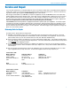
Installation
Installing the PA8 properly is simple, and only requires
attention to a few issues. The PA8 should be used in a
grounded metal rack. One open rack space should be
provided above and below the PA8 for proper ventila-
tion.
Non-Bridged Output
The standard PA8 configuration would have a balanced
output device (like the MM8 Matrix Mixer) driving each
channel of the PA8. The speaker is connected in the
non-bridged mode. Maximum output power is 10W into
4 Ohms, or 6W into 8 Ohms.
Figure 2 shows this configuration.
When driving the PA8 with an unbalanced source, the
(-) terminal is connected to the ground of the driving
signal, as well as the ground terminal of the PA8 input.
Figure 3 shows this configuration.
General Technical Description
Bridged Output
Two adjacent channels of a PA8 may be connected as
shown in Figure 4 to allow bridging operation. In the
bridged mode, the minimum speaker load is 8 Ohms,
and maximum power output is 20W into 8 Ohms. Note
that since the Channel Level controls of both bridged
channels will be active, they should be set to the same
level. The loudspeaker is connected to the (+) output
terminals of each channel, while the (-) outputs are left
unconnected.
Figure 5 shows bridging operation using an unbalanced
source.
Input
DRIVING DEVICE
PA8
GND
Output
GND
Input Output
DRIVING DEVICE
PA8
GND
GND
In 1 Out 2
DRIVING DEVICE
PA8
Out 1In 2
GND
GND
In 1 Out 2
DRIVING DEVICE
PA8
Out 1In 2
GND
GND
Figure 2 - Balanced Input / Non-Bridged Output
Figure 3 - Unbalanced Input / Non-Bridged Output
Figure 4 - Balanced In / Bridged Out
Figure 5 - Unbalanced In / Non-Bridged Out level is reached