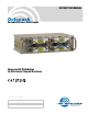
INSTRUCTION MANUAL Octopack Portable Receiver Multicoupler Power and RF Distribution for SRa Series Compact Receivers Fill in for your records: Serial Number: Purchase Date: Rio Rancho, NM, USA www.lectrosonics.
OCTOPACK 2 LECTROSONICS, INC.
Receiver Multicoupler FCC Compliance This device complies with Part 15 of the FCC Rules. Operation is subject to the following two conditions: (1) This device may not cause harmful interference, and (2) this device must accept any interference received, including interference that may cause undesired operation. The Octopack has been tested and found to comply with the limits for a Class B digital device, pursuant to Part 15 of the FCC Rules.
OCTOPACK Table of Contents General Technical Description...........................................................................................................................................................5 Control Panel.......................................................................................................................................................................................6 Battery Panel.......................................................................................
Receiver Multicoupler General Technical Description To address an increasing demand for more wireless channels in location production, the Octopack combines up to four SRa Series compact receivers into a lightweight, rugged assembly with self-contained power supply, power distribution and antenna signal distribution. This versatile production tool provides up to eight audio channels in a tiny package ready to work in applications from production cart to a portable mixing bag.
OCTOPACK Control Panel RF Signal Distribution Each antenna input is routed through a high quality RF splitter to coaxial leads on the control panel. Gold plated right angle connectors mate to the SMA jacks on SRa Series receivers. Frequencies of the installed receivers should be within the frequency range of the antenna multicoupler. Power Indication The power switch locks in position to prevent accidental turn off.
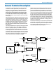
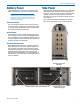
Receiver Multicoupler Battery Panel Side Panel The passband of the multicoupler is marked on the label on the housing cover next to the battery panel. IMPORTANT - The frequency of the receivers installed in the unit must fall within the passband indicated on the label. Serious signal loss can result if the receiver frequencies are outside the Octopack RF passband. External DC Power Eight balanced outputs are provided on the side panel of the multicoupler.
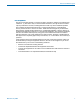
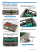
OCTOPACK Receiver Installation First install the SRUNI rear panel adapter. The mating 25-pin connector inside each slot on the Octopack provides power and audio connections. Gently insert the receivers into the slots. A guide around each internal connector centers the housing to align the connector pins. Plastic inserts are provided to cover empty slots. Sockets in the insert are sized to store loose antenna leads.
Receiver Multicoupler Receiver Removal Disconnect all four mounting screws on each receiver from the Octopack panel Normally the hex nuts on the coaxial RF leads are secured and removed by hand. The tool is provided if the nuts cannot be removed by hand. DO NOT overtighten the nuts with the wrench. A handy tool, constructed of Delrin, is provided to aid in removing the receivers and to loosen overly tightened coaxial connectors.
OCTOPACK Antenna Power Jumpers Power for Lectrosonics remote RF amplifiers is provided by DC voltage from the power supply passed directly to the BNC jacks on the control panel. An illuminated switch on the left side of the control panel enables and disables the power. A 300 mA polyfuse protects against excessive current in each BNC output. Antenna power switch glows red when DC power is enabled.
Receiver Multicoupler Antenna Bandwidth and Requirements The design of Lectrosonics wideband multicouplers helps deal with a changing RF spectrum, however, it also introduces the requirement for specific or more advanced antennas to provide maximum operating range. Simple whip antennas cut to a single frequency block are inexpensive and effective at covering a 50 to 75 MHz band, but will not provide adequate coverage for the entire range of a wideband antenna multicoupler.
OCTOPACK Antenna/Block Reference Chart The lengths shown are specifically for the A8U whip antenna with a BNC connector, as determined by measurements with a network analyzer. The optimal length of the element in other designs will likely be different than those shown in this table, but since the bandwidth is typically wider than the specified block, the exact length is not critical for useful performance.
Receiver Multicoupler Replacement Parts & Accessories P1246 Delrin tool for receiver removal and loosening coaxial antenna leads P1139 Blank slot cover 21746 Power cable with locking, right angle connector to stripped and tinned; 12 inch length A8U KIT Whip Antenna with BNC Connector and color coded end caps. Includes cutting template and table for all frequency blocks.
OCTOPACK Optional Accessories Coaxial Cables A variety of low loss coaxial cables are available to avoid signal loss through longer runs between antenna and receiver. Lengths include 2, 15, 25, 50 and 100 foot lengths. The longer cables are constructed of Belden 9913F with special connectors that terminate directly to BNC jacks, eliminating the need for adapters that can introduce additional signal loss.
Receiver Multicoupler Troubleshooting SYMPTOM POSSIBLE CAUSE NO POWER LED INDICATION 1) Power switch in the OFF position. 2) Batteries low or dead 3) External DC source too low or disconnected NOTE: If the power supply voltage drops too low for normal operation, the LCD on the receivers will display a “Low Battery” warning every few seconds. When the voltage drops to 5.5 volts, the LCD will dim and the audio output level of the receivers will decrease.
OCTOPACK Specifications RF Bandwidth (3 versions): RF Gain Output Third Order Intercept: 1 dB Compression: Antenna Inputs: Antenna Power: Receiver RF feeds: Internal Battery Type: External Power Requirement: Power Consumption: Dimensions: Weight: Assembly only: With 4-SRa5P receivers: Low: 470 to 691 MHz Mid: 537 to 768 MHz (export) High: 640 to 862 MHz (export) 0 to 2.
Receiver Multicoupler Service and Repair If your system malfunctions, you should attempt to correct or isolate the trouble before concluding that the equipment needs repair. Make sure you have followed the setup procedure and operating instructions. Check the interconnecting cables and then go through the Troubleshooting section in this manual. We strongly recommend that you do not try to repair the equipment yourself and do not have the local repair shop attempt anything other than the simplest repair.
OCTOPACK 18 LECTROSONICS, INC.
Receiver Multicoupler Rio Rancho, NM 19
LIMITED ONE YEAR WARRANTY The equipment is warranted for one year from date of purchase against defects in materials or workmanship provided it was purchased from an authorized dealer. This warranty does not cover equipment which has been abused or damaged by careless handling or shipping. This warranty does not apply to used or demonstrator equipment. Should any defect develop, Lectrosonics, Inc. will, at our option, repair or replace any defective parts without charge for either parts or labor.