
Owner manual


Watertight Miniature UHF Belt-Pack Transmitter
Rio Rancho, NM
9
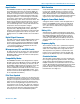
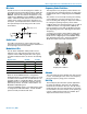
Mic Jack
TheMicJackisa2.5mmmicroplugthatiswiredtoac-
commodatetwo-wirepositivebiaslavalieres.Whilethe
M152-WP(waterproof)isspecicallydesignedforthe
MM400C, other two-wire lavaliere microphones can be
adaptedtotheMM440CusingtheWPMC-3orWPMC-
10kits.ASwitchcraft850connector(LectrosonicsP/N
21357)canbeusedinanemergencythoughitisnot
waterproof.(SeeReplacementPartsandAccessories.)
The equivalent input circuit wiring for the Mic Jack is
shown below:
Audio Level
The Audio Level Control is used to adjust the audio
input level from the microphone for proper modulation of
the output signal from the transmitter.
Modulation LEDs
The two bicolor Modulation LEDs provide a visual
indication of the audio signal level input from the mi-
crophone. These LEDs can glow either red or green
to indicate modulation levels as shown in the following
chart.
Signal Level -20 LED -10 LED
Lessthan-20dB Off Off
-20dBto-10dB Green Off
-10dBto+0dB Green Green
+0dBto+10dB Red Green
Greaterthan+10db Red Red
WhenthePowerON/OFFSwitchisconguredfor
Audio Mute Mode, the -10 Modulation LED is also used
to indicate if the transmitter is in an audio muted, or an
unmuted condition. In Audio Mute Mode, if the Power
ON/OFFswitchissettoOFF,thetransmitterremains
powered up; however, the audio is muted and the -10
Modulation LED blinks green.
IfthePowerON/OFFswitchissettoONandtheswitch
is configured for Audio Mute Mode, -10 and -20 LEDs
operate normally to indicate audio level.
Mic
Jack
330pF 330pF
FB
FB
100
2k
2k
30uF
6V Mic Bias
To Mic Amp
2k
2.2nF
Frequency Select Switches
1.6M 100K
0
1
2
3
4
5
6
7
8
9
A
B
C
D
E
F
0
1
2
3
4
5
6
7
8
9
A
B
C
D
E
F
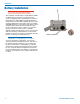
Frequency Select Switches
Two 16-position rotary Frequency Select Switches are
used to select the operating frequency, for setting Com-
patiblityModesandforconguringthePowerON/OFF
switch.
The switches are accessed by loosening the retaining
screw holding the cover plate, lifting the cover away
fromthehousingandrotatingittoexposetheswitches.
For setting the operating frequency, the left switch
(1.6MHz)adjuststheoperatingfrequencyupordownin
1.6MHzincrements.Therightswitch(100kHz)ad-
juststhefrequencyupordownin100kHzincrements.
(See Operating Instructions, Adjusting the Transmitter
Frequency.)
A sequence of Frequency Select Switch settings and
PowerON/OFFtogglesareusedtosetCompatibility
ModesandforconguringthePowerON/OFFswitch.
(See Operating Instructions, Setting Compatibility
Modes and Power Switch Function Selection.)
Antenna
Thepermanently-mounted,exiblesteelcableantenna
iscutto1/4wavelengthofthecenterofthefrequency
block(thefrequencyrange)ofthetransmitter.
Belt Clip
The belt clip may be removed for special applications
by gently spreading the spring wire clip and pulling
the ends out of the holes in the case. The clip can be
installed in either the up or down position so that when
the transmitter is worn, the antenna can be pointing up
or down. Replacement belt clips are available. (See
Replacement Parts and Accessories.)