
User's Manual


Digital IEM System
Rio Rancho, NM
15
Initial Setup
Connect AC power to the M4T transmitter using the
provided power cable. To ensure that the power cable
can not come loose, use the provided wire retainer. By
placing the retainer above the cable and then pressing
down, the retainer can not come loose.
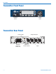
Attach the supplied antenna to the antenna port on the
back of the M4T, and position it pointing upright while
tightening the knurled nut at the base of the antenna.
If you are rack-mounting one or more M4T transmit-
ters, please see the section on installing rack mounting
hardware (below).
Connect your audio inputs via the XLR connectors.
Note that like a mixing console, the inputs are oriented
right to left, inputs 1-4. If you are feeding the transmit-
ter with analog audio signals, connect your channel 1
to input 1, channel 2 to input 2 and so on.
IfyouaresendingdigitalAES/EBUsignalstotheM4T
transmitter,notethatAES/EBUlinescarrytwochan-
nels on a single XLR connection. Therefore, channels
1 & 2 would be connected to input 1, and channels 3
& 4 are connected to input 2. Note also that in order
to change between analog and digital inputs, use the
front panel menus (see below).
Powering the Unit
ON and OFF
Once you have connected AC power, the antenna,
and your audio lines, apply power to the M4T using
the switch on the front panel. The LCD displays a brief
logo and graphic, followed by the model number, de-
scription and firmware version:
AfterthePowerUpSequence,theMainWindowap-
pears and the M4T is ready for operation.
To turn the transmitter off, simply return the front panel
power switch to the “off” position.
LCD
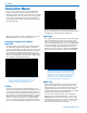
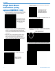
TheMainWindowshowsthefollowing:
• Operating frequency
(Frq1, Frq2, etc. for 4-ch or Split 4-ch operation
(Frq1a, Frq1b, Frq2a, etc. for 2-ch operation - see
Channel Setup below)
• Audio level meters for either two or four channels
(depending on how the M4T is set up - see Chan-
nel Setup below)
• Headphone monitoring channels as indicated by
the small headphone icons next to the level meters
for those channels.
Audio Signal Monitoring
The signals at the inputs can be monitored in two
ways: using the LCD bar-graph meters for levels and
with headphones for listening to the actual signals. The
LCD bar-graph meters show the audio level range from
-60to0dB.Whenthesignalexceedstheavailable
input headroom, the bar graph indicates this with a
bright “!” at the top of the bar on that channel. Because
this is a digital system, overloads should be carefully
avoided as to prevent signal distortion at the convert-
ers.
NOTE: Do not “drive” this transmitter as you might
be tempted to do with an analog IEM system. Gener-
ally, it is best to leave 3 dB of headroom above your
strongest peaks to ensure that you are not clipping the
signals.
Clipping Indicator
Tomonitortheaudiosignal/s,plugintotheheadphone
jack with headphones or earbuds. Push the volume
knob so that it “pops out” for level adjustment. To
selectthechannel/sforlistening,pressthenumbered
button/s1-4belowthosechannels.Eitheroneortwo
channelsatatimecanbemonitored.Whenonechan-
nel is chosen, it is panned center in the headphone
stereoeld.Whentwochannelsarechosenbypress-
ing both buttons at the same time, they are panned
hard left & right in the headphones.
CAUTION: Start with the monitor volume
at a low setting before plugging in your
headphones or earbuds - excessive volume
can damage your hearing.