M185 BELT-PACK TRANSMITTER OPERATING INSTRUCTIONS and trouble-shooting guide LECTROSONICS, INC.
INTRODUCTION Thank you for selecting the Lectrosonics M185 transmitter. This transmitter represents over 70 years of combined experience in the design of RF devices and sets new standards for operational convenience, flexibility and mechanical ruggedness. The M185 transmitter features all metal construction and operates on high band frequencies from 150mHz to 216mHz.
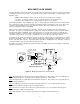
GENERAL TECHNICAL DESCRIPTION The M185 transmitter is comprised of four major functional subsystems: the input compressor, the mic preamp/gain control, the compandor, and the RF transmitter (see block diagram below). The input compressor is a low distortion shunt FET compressor operating before the mic preamp.
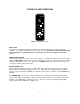
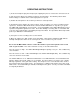
CONTROLS AND FUNCTIONS LECTROSONICS M 185 ON MUTE OFF LEVEL LIMIT MIC LEVEL Figure 2 - M185 Front Panel INPUT JACK The input on the M185 accommodates virtually every lavalier, hand-held or shotgun microphone available. Use a Switchcraft TA5F connector on the cord. See the separate sheet titled "M185 Input Jack Configuration" regarding the correct connections for various microphones, and other sources. ON/MUTE/OFF SWITCH Turns the battery power on and off.
CONTROLS AND FUNCTIONS (cont’d) Since the internal circuits are all tightly regulated and the RF output stage has a separate discrete regulator, the transmitter will continue to operate to a battery voltage of 6.5 Volts. From 6.5 Volts to 6 Volts, the transmitter will still operate, but with degraded performance.
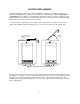
BATTERY REPLACEMENT The M185 transmitter is powered by a standard alkaline 9 Volt battery. It is important that you use ONLY an ALKALINE battery for longest life. Standard zinc-carbon batteries marked "heavy-duty" or "long-lasting" are not adequate. They will provide only about 4 hours of operation. Similarly, ni-cad rechargeable batteries only provide 4 hours of operation or less, and will also run down quite abruptly. Alkaline batteries provide about 15 hours of operation.
OPERATING INSTRUCTIONS 1) Insert the microphone plug into the input jack, aligning the pins; be sure that the connector locks in. 2) Turn the power switch to the "MUTE" position on the transmitter. The "MUTE" position allows internal voltages to stabilize before audio signal paths are opened. 3) Position the microphone in the location you will use in actual operation. 4) Keeping the power switch in the "mute" position, speak as loudly as you expect you will in normal system use.
M185 INPUT JACK WIRING The wiring diagrams shown on the attached sheet represent the basic wiring necessary for the most common types of microphones and other audio inputs. Some microphones may require extra jumpers or a slight variation on the diagrams shown. Caution - When wiring the connector, do not use the connector body for any electrical connections. A common mistake is to use the connector body as an audio ground. The connector body is already used as an RF ground and no other use is permitted.
TROUBLESHOOTING Before going through the following chart, be sure that you have a good battery in the transmitter. It is important that you follow these steps in the sequence listed. SYMPTOM POSSIBLE CAUSE TRANSMITTER BATTERY LED OFF 1) Battery is inserted backwards. 2) Battery is dead. NO TRANSMITTER MODULATION LEDs 1) Gain control turned all the way down. 2) Battery is in backwards. Check power LED. 3) Mic capsule is damaged or malfunctioning. RECEIVER RF LAMP OFF 1) Transmitter not turned on.
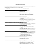
SPECIFICATIONS AND FEATURES Operating frequencies: 150 to 216 MHz RF Power output: 50 mW Deviation: ±15 kHz (max) Spurious radiation: 55 dB below carrier Equivalent input noise: -126 dBV Input level: Nominal 2 mV to 300 mV (before compression) 30 Volt max.
SERVICE AND REPAIR If your system malfunctions, you should attempt to correct or isolate the trouble before concluding that the equipment needs repair. Make sure you have followed the setup procedure and operating instructions. Check out the inter-connecting cords and then go through the TROUBLE SHOOTING section in the manual We strongly recommend that you do not try to repair the equipment yourself and do not have the local repair shop attempt anything other than the simplest repair.
LIMITED ONE YEAR WARRANTY The equipment is warranted for one year from date of purchase against defects in materials or workmanship provided it was purchased from an authorized dealer. This warranty does not cover equipment which has been abused or damaged by careless handling or shipping. This warranty does not apply to used or demonstrator equipment. Should any defect develop, we will, at our option, repair or replace any defective parts without charge for either parts or labor.