
User's Manual

LR
LECTROSONICS, INC.
14
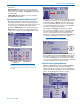
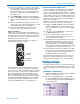
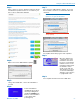
Press the MENU/SEL button to pause the scan.
Use the UP and DOWN buttons to scroll the marker
through the graphical image. Press MENU/SEL to
increase the resolution while scrolling.
Use arrow buttons to scroll marker
Press MENU/SEL to increase
the resolution in scrolling.
Press MENU/SEL to zoom in on the image. Scroll us-
ing the buttons as described above.
RF energy Clear spectrum
After scrolling the marker to a spot in the clear spec-
trum in the display, press BACK to open a menu with
three options.
Use the arrow keys to select the option, then press
MENU/SEL to store the setting and return to the Main
Window.
• Keep stores the new frequency and returns to
the Main Window.
• Keep + IRSync stores the frequency, then moves
to the IR Sync screen. Copy the frequency to the
transmitter and then press BACK to return to the
Main Window.
• Revert discards the new frequency and returns
to the Main Window.
• Press BACK to return to scanning
5) Set Up Transmitter to Matching Frequency
and Compatibility Mode
If you have not already set the frequency on the
transmitter in the previous procedures, use IR Sync or
complete the settings manually.
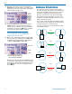
Lectrosonics transmitters with IR Sync:
On the LR receiver, navigate to IR Sync on the menu
and press the MENU/SEL button. Hold the transmitter
and receiver fairly close to each other (within two feet
or so) and position them so the IR ports are facing one
another. Press the UP arrow on the receiver to initiate
the transfer of settings. The receiver will display a mes-
sage when the settings have been received.
Other transmitters:
Frequency, input gain, etc, are set with the controls on
the transmitter. The correct compatibility mode must
also be selected on the receiver.
6) Adjust Transmitter Input Gain
NOTE: This adjustment is very important, since
it will determine the signal to noise ratio and
dynamic range that the system will deliver.
Lectrosonics transmitters with LCD interface:
The LEDs on the control panel provide an accurate
indication of modulation level to assist in adjusting the
input gain. The LEDs will glow either red or green to
indicate modulation levels as shown in the following
table. Full modulation is achieved at 0 dB, when the
“-20” LED first turns red. The limiter can cleanly handle
peaks up to 30 dB above this point.
Signal Level -20 LED -10 LED
Less than -20 dB Off Off
-20 dB to -10 dB Green Off
-10 dB to +0 dB Green Green
+0 dB to +10 dB Red Green
Greater than +10 dB Red Red
NOTE: It is best to go through the following
procedure with the transmitter in the standby
mode so that no audio will enter the sound
system or recorder during adjustment.
1) With fresh batteries in the transmitter and power
the unit on in the standby mode (a brief press on
the power switch with L-Series transmitters).
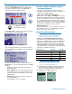
2) Navigate to the Gain setup screen.
Gain
LineIn
Freq.
ProgSw
-40
-20
0
Gain
25