
User's Manual

LMb
LECTROSONICS, INC.
6
5
623.400
-40
-20
0
A
FCCID:DBZLMBC1
Lectrosonics, Inc.
Made in U.S.A.
IC: 8024A-LMBC1
614.4 - 691.1 MHz
Model: LMBC1
S/N XXXXX
-20
-10
BAT
Operating Instructions
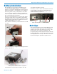
Battery Status LED Indicators
Alkaline, lithium or rechargeable batteries can be used
to power the transmitter. The type of batteries in use are
selectable in a menu on the LCD.
When alkaline or lithium batteries are being used, the
LED labeled BATT on the keypad glows green when the
batteries are good. The color changes to red when the
they are nearing the end of life. When the LED begins to
blink red, there will be only a few minutes remaining.
The Power/Function LED on the top panel will mirror the
keypad LED unless the programmable switch is set to
the Mute or Talkback mode, and the switch is turned on.
The exact point at which the LEDs turn red will vary
with battery brand and condition, temperature and
power consumption. The LEDs are intended to simply
catch your attention, not to be an exact indicator of
remaining time.
A weak battery will sometimes cause the LEDs to glow
green immediately after the transmitter is turned on, but
it will soon discharge to the point where the LED will
turn red or the unit will turn off completely.
Rechargeable batteries give little or no warning when
they are depleted. If you wish to use these batteries in
the transmitter, you will need to manually keep track of
the operating time to prevent interruptions caused by
dead batteries. Start with a fully charged battery, then
measure the time it takes for the Power LED to go out
completely.
NOTE: The battery timer feature in many
Lectrosonics receivers is very helpful in measuring
battery runtime when using rechargeable batteries.
Refer to the receiver instructions for details on
using the timer.
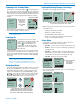
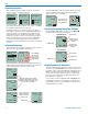
Powering On in Operating Mode
Press and hold the Power Button for several seconds
until a counter on the LCD progresses from 1 through
3, followed by a display of the model, firmware version,
frequency block and compatibility mode.
Hold
for
Rf On
...3
Blk. 19
V1.00
LMB
Hybrid
5
494.500
-40
-20
0
1
b 19
When you release the button, the unit will be operation-
al with the RF output turned on and the Main Window
displayed. Only the second and third screens will ap-
pear when the programmable function switch is used to
turn on the power.
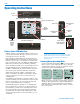
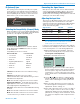
Slide door
outward
to open
battery
door
Input Jack
Power/Function
LED
Programmable
Switch
Modulation
LEDs
Belt clip mounting hole
Battery Status LED Battery icon
Power Button
Reserved for Future Use
IR Sync
Port
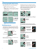
Menu
navigation
buttons
-20
-10
BAT
Move switch
toward the white
dot to turn it on
RF Indicator