
User's Manual

LMb
LECTROSONICS, INC.
10
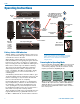
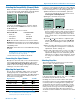
Selecting Frequency
The setup screen for frequency selection offers several
ways to browse the available frequencies.
Freq.
b 19
494.500
51
Press MENU/
SEL to select
one of four
fields to make
adjustments
Gain
Freq.
ProgSw
Compat
Each field will step through the available frequencies in
a different increment. The increments are also different
in the 25 kHz mode from the 100 kHz mode.
Freq.
b 19
494.500
51
Freq.
b 19
494.500
51
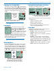
These two fields step in 25 kHz
increments when the step size is 25
kHz and 100 kHz increments when
the step size is 100 kHz.
Freq.
b 19
494.500
51
Freq.
b 19
494.500
51
These two fields
always step in the
same increments
1 MHz steps
1 band steps
A fraction will appear next to the hex code in the setup
screen and in the main window when the frequency
ends in .025, .050 or .075 MHz.
494.525
-40
-20
0
b 19
MUTE
1
4
51
Freq.
b 19
494.525
51
1
4
Fraction appears
next to hex code
in 25 kHz mode
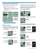
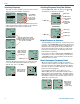
Selecting Frequency Using Two Buttons
Hold the MENU/SEL button in, then use the and
arrow buttons for alternate increments.
Freq.
b 19
494.500
51
1 band steps
1.6 MHz steps to
nearest 100 kHz
channel
10 MHz steps
100 kHz steps
to next 100 kHz
channel
100 kHz Mode
Freq.
b 19
494.525
51
1
4
1 band steps
1.6 MHz steps
10 MHz steps
100 kHz steps
25 kHz Mode
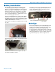
Helpful Features on Receivers
To aid in finding clear frequencies, several Lectrosonics
receivers offer a SmartTune feature that scans the tun-
ing range of the receiver and displays a graphical report
that shows where RF signals are present at different
levels, and areas where there is little or no RF energy
present. The software then automatically selects the
best channel for operation.
Lectrosonics receivers equipped with an IR Sync func-
tion allow the receiver to set frequency, step size and
compatibility modes on the transmitter via an infrared
link between the two units.
About Overlapping Frequency Bands
When two frequency bands overlap, it is possible to
select the same frequency at the upper end of one and
the lower end of the other. While the frequency will be
the same, the pilot tones will be different, as indicated
by the hex codes that appear.
In the following examples, the frequency is set to
494.500 MHz, but one is in band 470 and the other in
band 19. This is done intentionally to maintain compat-
ibility with receivers that tune across a single band. The
band number and hex code must match the receiver to
enable the correct pilot tone.
Freq.
b 19
494.500
51
Freq.
b470
494.500
F4
Make sure the
band number
and hex code
match the
receiver setting