
User's Manual

LM/IM
LECTROSONICS, INC.
8
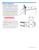
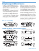
Adjusting the Transmitter Frequency
If you are experiencing interference from another signal
on your operating frequency, you may need to change
the operating frequency of your system. This is done
through two Frequency Select Switches located on the
left side of the transmitter case. (See Frequency Select
Switch Locations.)
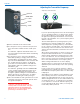
The left switch adjusts the operating frequency of the
transmitter up or down in 1.6 MHz steps. The right
switch adjusts the operating frequency of the transmit-
ter up or down in 100 kHz steps. It is suggested to use
the metering on the associated receiver to find a clear
channel. Turn the transmitter off and leave the receiver
turned on.
All 400 Series (and a number of earlier receivers) offer
front panel LCDs that indicate the correct transmitter
switch settings, and built in scanning functions to help
locate clear channels. Use the scanning functions on
these receivers to find a clear channel, then switch both
the receiver and transmitter to the Frequency Select
Switch settings indicated in the receiver’s display.
The R400 Series receivers have an autotune function
(SmartTune) that automatically locates clear operating
channels.
If your receiver does not have an autotune or built in
scanning function, manually tune the receiver across its
band and find a frequency where little or no RF activity
is displayed.
After finding a clear channel, set the transmitter to this
new frequency, then turn it on and make sure the RF
signal is strongly indicated at the receiver. Be sure the
switch settings between the receiver and transmitter are
set exactly the same. If, for example, the 100K switch
is one click above or below the desired frequency, the
receiver will indicate RF, but no audio (or severely dis-
torted audio) will be produced.
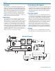
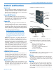
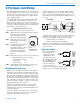
Frequency Select Switches
Input Jack
AUDIO LEVEL
Control
-20 LED
-10 LED
4) Set the transmitter Power switch to ON.
5)
For microphone users, position the microphone in
the location where it will be used in actual opera-
tion.
For musicians, adjust the instrument volume con
-
trols to the highest levels that would be used during
a performance.
6)
For microphone users, observe the Modulation
LEDs while speaking or singing at the same voice
level that will be used during the program. Gradu-
ally rotate the AUDIO LEVEL control clockwise until
the -10 LED glows green and the -20 dB glows
green with occasional red flickers. This indicates
full modulation and is the optimum setting for the
transmitter’s gain.
For musicians, gradually rotate the AUDIO LEVEL
control clockwise while playing the loudest notes
that will be played during the performance. Al-
though the optimum setting is for both Modulation
LEDs to glow green, it is ideal for the -20 LED to
briefly flicker red during the loudest passages.
7) Once the transmitter’s audio gain has been set, the
remaining components of the audio system can be
energized and adjusted.
Warning: DO NOT use the audio level
control for controlling the volume of your
sound system or recorder levels. This gain
adjustment matches the transmitter gain
with the user’s voice level and microphone
positioning, or instrument output.
0
1
2
3
4
5
6
7
8
9
A
B
C
D
E
F
0
1
2
3
4
5
6
7
8
9
A
B
C
D
E
F
1.6M 100K