LE8 * LOGIC CONTROLLED EQUALIZER MODULE OPERATING INSTRUCTIONS and trouble-shooting guide LECTROSONICS, INC.
INTRODUCTION Thank you for purchasing the Lectrosonics LE8 Logic Controlled Equalizer. The LE8 represents a significant advance in equalization technology. The LE8, when used in an automatic Modular Audio Processor system, provides an economical solution to the problem of multiple microphone equalization and notch filtering. Each of up to eight microphones may be equalized using a four band equalizer. In addition, three variable frequency notch filters are available for each microphone.
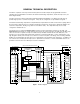
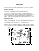
GENERAL TECHNICAL DESCRIPTION The LE8 is comprised of five major functional subsystems: the balanced input, the programmable four band equalizer, three programmable notch filters, the balanced and floating output driver, and the microprocessor (see block diagram below). The input circuit of the LE8 is a fully balanced, RF filtered differential amplifier. The balanced circuit topology provides high rejection of common mode signals. It may also be configured to accept unbalanced signals.
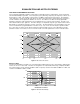
EQUALIZATION AND NOTCH FILTERING FOUR BAND PROGRAMMABLE EQUALIZER The four band programmable equalizer contains both low and high frequency shelving filters, as well as mid bass and mid treble bandpass type filters. The low frequency (bass) filter hinge frequency (the frequency at which cut or boost begins) is 1 kHz. The mid bass center frequency is 300Hz, and the Q of the filter is 0.33. The mid treble center frequency is 3 kHz, and the Q of the filter is also 0.33.
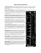
FRONT PANEL DESCRIPTION ACTIVE/BYPASS SWITCH - The Active/Bypass switch provides the user a means to bypass both the equalization and notch filters in the LE8. All other functions and controls are active (consistent, of course, with the position of the Operate/New Setting switch). When the Active/Bypass switch is in the Bypass mode, the Link Out signal is brought to logic low.
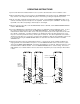
REAR PANEL DESCRIPTION LOGIC INPUTS 1-8 - The Logic Inputs provide the input for a contact closure (or other means) to indicate to the LE8 what filter set should be loaded. A contact closure (i.e. a short) between the Logic Input "+" and Logic Input "-" is needed to activate the input (this is referred to as "active low logic"). Logic Input "+" is connected through a 10K Ohm resistor to the internal +5 Volt supply, and Logic Input "-" is connected to the internal digital ground.
INSTALLATION SYSTEM INSTALLATION - The LE8 module, like any other equalization module, will normally be driven from either the AC1 Main Output, or from an EQN1 (if there is one in the system). The output signal from the LE8 should be routed to a DP1 (if there is one in the system), an XO2 or XO3 (if there is one in the system), or to the system power amplifier input. MECHANICAL INSTALLATION Prior to installing the LE8 module into the mainframe, the position of the LINK mode jumper must be set.
OPERATING INSTRUCTIONS 1) Connect the LE8 into the Modular Audio Processor system as described above in the Installation section. 2) On the AC1 Main module, note the position of the THRESHOLD control and then turn the THRESHOLD control fully clockwise. This will prevent multiple microphones from turning on during the adjustment procedure. 3) On all of the AP4 or EP4 Mic Preamp modules in the system, set the PRIORITY/AUTO/DIRECT switch on all channels to AUTO, except the microphone to be equalized.
NOTE: To restore the original factory settings, hold down the NOTCH FILTER 3 and STORE SETTING buttons while turning on the MAIN POWER SWITCH on the AC1, EC1, or SC1. The EQ and NF LEDs will blink. Now turn the MAIN POWER SWITCH off, release the buttons, and turn the MAIN POWER switch back on. Memory is now reset to original factory settings. 7) Using the PRIORITY/AUTO/DIRECT switch on the AP4 or EP4, switch the current microphone to AUTO, and the next microphone to be adjusted to DIRECT.
TROUBLESHOOTING SYMPTOM POSSIBLE CAUSE Active Logic LEDs cycle through 1-8 No Active Logic Input detected Equalizer/Notch Filter buttons and Adjust control do not respond Operate/New Setting switch in Operate position. Switch to New Setting Equalizer/Notch Filter buttons and Adjust control respond, but sound doesn’t change. Active/Bypass switch in Bypass position. Switch to Active. "Clicking" sound heard when filters switch. Output of MAP system too low (too much gain at power amp).
SERVICE AND REPAIR If your system malfunctions, you should attempt to correct or isolate the trouble before concluding that the equipment needs repair. Make sure you have followed the setup procedure and operating instructions. Check out the inter-connecting cords and then go through the TROUBLE SHOOTING section in the manual We strongly recommend that you do not try to repair the equipment yourself and do not have the local repair shop attempt anything other than the simplest repair.
SPECIFICATIONS Input: Type Impedance Max input level Balanced and RF filtered 20K balanced or unbalanced +20dBu Output: Type Impedance Max output level Balanced, floating, and RF filtered 100 Ohms balanced, 50 Ohms unbalanced +20dBu THD @ +4dBu, 20-20kHz <0.05% IMD @ +4dBu, 60/7kHz mixed 4:1 <0.
LIMITED ONE YEAR WARRANTY The equipment is warranted for one year from date of purchase against defects in materials or workmanship provided it was purchased from an authorized dealer. This warranty does not cover equipment which has been abused or damaged by careless handling or shipping. This warranty does not apply to used or demonstrator equipment. Should any defect develop, we will, at our option, repair or replace any defective parts without charge for either parts or labor.