
Manual


1
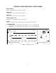
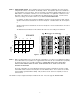
STEP 5 - Setting the DIP switches Upon completion of the chart you will have a grid which can now be used for
setting the DIP switches on the LCA16. See Example 2 below. Each speaker output on the LCA16 has a
set of dip switches on the front panel. There are two banks of 16 switches aligned vertically above a set of
LED indicators. The left bank of switches is for "A" level attenuation. The right bank of switches is for "B"
attenuation. DIP switches are set to the ON position by depressing them to the right. You will set these
switches according to the A and B notations on your LCA16 SYSTEM WORKSHEET.
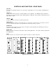
For example, according to the worksheet in Example 2, speaker 1 has two microphones which it affects.
Speaker 1 will need to be attenuated to "A" level for microphone 1 and attenuated to "B" for microphone
2.
Speaker 2 will need to be attenuated to "B" level for microphones 1 and 3 and attenuated to "A" level for
microphone 2.
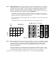
The illustrations below indicate how the switches will need to be set according to the worksheet.
DOT INDICATES "ON" CONDITION.
Assigned
Mics
7A 7B 8A 8B
SPEAKER
0
5
1
2
9
15
OPEN OPEN
OPEN OPEN
OPENOPEN
OPENOPEN
1 2 3 4
3
7A
4
5
1
2
3
7B
0
5
2
A B
6
9
7
15
8
B A
0
5
9
10
9
15
11
LOGIC
8A
B
12
13
3
8B
0
5
14
9
15
15
16
Figure 7 - Example 2
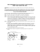
STEP 6 - Make your initial settings for the "A" and "B" levels of attenuation. If you have not yet determined a starting
level of attenuation for your speakers, it is suggested that all "A" levels be set for full attenuation (completely
off) and the "B" levels set for 5 to 9dB of attenuation. PLEASE NOTE THAT THE "A" LEVEL WILL
ALWAYS TAKE PRIORITY OVER "B" LEVEL, SO BE CERTAIN THE "A" LEVEL IS SET TO THE
GREATER ATTENUATION.
The levels of attenuation are set by adjusting the small recessed pots found between each pair of output
channel DIP switches located on the front panel. See the illustration above. These controls are set with a
small screwdriver (provided with the LCA16). Fully clockwise sets the channel to completely off. Set all
active channels.
The LCA16 is now pre-configured and may be installed in the rack. Proceed to page 10, INSTALLATION.
7