
Manual


PRE-CONFIGURING THE LCA16 PRIOR TO INSTALLATION,
16 or FEWER MICS PER LCA16
This procedure should be performed prior to installation. The LCA16 SYSTEM WORKSHEET (Appendix 2) will
assist you in setting up the LCA16 before going on site. While the actual setup is quite simple, it is recommended
that you use this worksheet, especially if this is your first installation using the LCA16 Logic Controlled Amplifier.
Using the LCA16 SYSTEM WORKSHEET
PROCEDURE 1 - Use this procedure if you have 16 or fewer microphones per LCA16 in this installation. This
procedure assumes a 1:1 relationship between microphones and logic terminals. If you have more than 16
microphones per LCA16, then skip this section and use procedure 2.
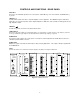
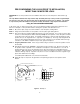
To fill out this chart, you need a floor plan of the room showing both speaker and microphone placement. See
below for an example of a floor plan with notations showing mics, speakers, and attenuation zones.
STEP 1 - On your floor plan, assign consecutive numbers to each microphone, starting with #1.
STEP 2 - Assign consecutive numbers to each speaker on the floor plan, again starting with #1.
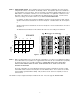
STEP 3 - On your LCA16 SYSTEM WORKSHEET, assign the microphones to logic inputs in the first column on
the left. Simply transfer the microphone numbers from your floor plan to the crossed boxes. See
Example 1.
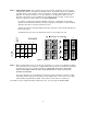
STEP 4 - Assigning Attenuation Levels In this step you will be noting in each box how much the speakers will
be affecting each microphone.
4A Start with the box where the SPEAKER 1 column intersects the microphone 1 (logic input 1) row. Check you
floor plan. If speaker 1 will be a potential source of feedback for microphone 1, then mark that box. Use an
"A" for speakers which are very close to the microphone and a "B" for those which are located further from
the microphone. While still referring to the floor plan, move down to the next box in the speaker 1 column
where it intersects the microphone 2 row. If speaker 1 will also affect microphone 2, then mark that box
accordingly.
If this speaker will have no effect, then leave the box blank.
4B Repeat this step for every box in the grid where a speaker and microphone/logic input intersect.
1
2
3
1 2 3 4
Assigned
Mics
SPEAKER
1
2
3
A
B
B
A
B
CHAIR
SPEAKER
MICROPHONE
EXCERPT FROM
ROOM PLAN
A LEVEL ATTENUATION ZONE FOR MIC 1
B LEVEL ATTENUATION ZONE FOR MIC 1
TABLE
STEP 4
STEP 3
1
2
3
SPKR
1
SPKR
2
Figure 6 - Example 1
6