
Manual


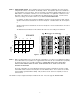

ATTENUATION DIP SWITCHES (located behind front panel cover)
These switches are used to programs which microphone (or microphones) connected to the 16 LOGIC INPUTS will
trigger the "A" and "B" attenuation levels for each of the 16 output channels. Four banks of switches (eight
switches per bank) are allocated to each channel. Two of the switch banks (16 switches) trigger the "A" attenuation
level, the other two switch banks trigger the "B" attenuation level. The switch number is printed on the circuit board
alongside the switch assemblies (disregard the numbers printed on the switch assembly itself).
ATTENUATION LEVEL CONTROLS (located between the DIP switch assemblies)
These control the amount of "A" and "B" level attenuation for each output channel. "A" level attenuation always
takes priority over "B" level attenuation and, therefore, the "A" control must always be set to a higher setting than
the "B" control.
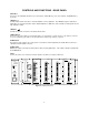
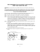
An enlarged view of the speaker #7 and #8 sections of the attenuation selection DIP switches and attenuation level
controls is shown below. The attenuation select switches provide the means to select which microphones will
attenuate each speaker and to what attenuation level. The output of each speaker amplifier may be attenuated
from 0dB to completely off by means of the two continuously variable preset adjustment potentiometers ("A" and
"B"). Therefore, each speaker may be attenuated by one or more microphones on either (or both) of the "A" or "B"
levels as shown in the examples on page 7 and 8.
SWITCH
NUMBERS
ATTENUATION CONTROL POTS
3A
1
1
1
0
5
1
1
2
2 2
9
2
2
3
O
3
O
3
15
O
3
O
3
P
P
P
P
E
E
E
E
DIP SWITCHES
4 4 4
4
4
N
5
5
N
5
3B
N
5
N
5
6
6 6
6
6
0
5
9
7
7 7
7
7
8 8 8
15 8
8
9
1
1
0
5
1
1
10
2
2
9
2
2
11
O
3
O
3
O
3
O
3
12
4 4
4A
4 4
15
P
P
P
P
E
E
E
E
13
N
5
N
5
N
5
N
5
0
5
4B
14
6 6
6 6
15
7 7
9
7 7
16
8 8
15
8 8
3A
1
1
0
5 1
1 1 1
1
0
5 1
1
1
3A
3A
1
1
0
3A
5 1
1
1
1
1
0
5 1
1
2
2 2
9
2
2
2
2
2
9
2
2 2
9
2
2
2
2 2
9
2
2
2
O
3
O
3
15
O 3
O
3
3
O
3
O
3
15
O
3
O
3
3
O
3
P
O
3
15
O
3
P
O
3
3
O
P
3
O
P
3
15
O
P
3
O
P
3
P
P
P P
P P
P
P
P
4 4
P
4
4
4
4
4
4
4
E
4 4
4
E
4 4
4
E
4
E
4
4
4
E
E
E E
E
E
E
E
E
E
E
E
3B
N
N
5
N
5
3B
N
5
N
5
5
N
5
N
5
3B
N
5
N
5
5
N
5
N
5
N
5
N
5
5
N
5
N
5
0
3B
5
N
5
5
6 6
6
6
6
6 6
6
6
6
0
5
0
5
6 6
0
5
6
6
6 6
6
6
6
9
9
7 7
9
7
7
7 7
7
9
7
7
7 7
7
7
7
7 7
7
7
7
8 8
15
8
8
8
8
8
15
8
8
8 8
15
8
8
8 8 8
15
8
8
8
1
1
0
5
1
1
9
1
1
0
5
1
1
9
1
1
0
5
1
1
9
1
1
0
5
1
1
2 2
9
2
2
10
2
2
9
2 2 10
POW ER
2
2
9
2 2 10
2 2
9
2 2
O
O 3 O 3
O
3
O
3
O
3
O
3
11
O
3
O
3
15
O
3
O
3 11
O
3
O
3
15
O
3
O
3
11
O 3 3
15
P
P
P
P
P
15
P
P
P
P
P
P
P
4
P
4
4A
P
4
P
4 12
P
4
E
4
4A
E
4
E
4
4 4
4A
E
4
E
4
12
4
E
4
4A
E
4
E
4
12
E
E
E E E
5
N
5
N
N
5 N 5
N
5
N 5
13
N
5
N
5
N
5
N
5 13
N 5
N
5
N
5 13
N
0
N
E
E
E
5 5
N
5
5
6
7
8
5
9
15
4B
0
6
7
8
6
7
8 16
15
14
6
7
8
6
7
8
5
9
15
4B
0
6
7
8
6
7
8
16
15
146
7
8
6
7
8
5
9
15
4B
0
6
7
8
6
7
8
16
15
14
6
7
8
6
7
8
9
15
4B
6
7
8
6
7
8
6
7
8
POWER
SIGNAL
PRESENT
1
2
3
4
5
6
7
8
O
P
E
N
5
9
15
3A
5
9
15
3B
3A 3B
4A 4B
0
0
ATTENUATION LE VEL
1
2
3
4
5
6
7
8
O
P
E
N
1
2
3
4
5
6
7
8
O
P
E
N
1
2
3
4
5
6
7
8
O
P
E
N
1
2
3
4
5
6
7
8
O
P
E
N
O
P
E
N
1
2
3
4
5
6
7
8
ATTENUATION LEVEL
1
2
3
4
5
6
7
8
5
9
15
3A
5
9
15
3B
0
0
O
P
E
N
1
2
3
4
5
6
7
8
O
P
E
N
1
2
3
4
5
6
7
8
1
2
3
4
5
6
7
8
O
P
E
N
O
P
E
N
1
2
3
4
5
6
7
8
ATTENUATION LE VEL
1
2
3
4
5
6
7
8
5
9
15
3A
5
9
15
3B
1
2
3
4
5
6
7
8
0
0
1
2
3
4
5
6
7
8
O
P
E
N
1
2
3
4
5
6
7
8
O
P
E
N
O
P
E
N
O
P
E
N
1
2
3
4
5
6
7
8
ATTENUATION LEVEL
1
2
3
4
5
6
7
8
5
9
15
3A
5
9
15
3B
0
0
O
P
E
N
1
2
3
4
5
6
7
8
O
P
E
N
1
2
3
4
5
6
7
8
0
1
2
3
4
10
5
6
7
8
9
O
P
E
N
O
P
E
N
1
2
3
4
5
6
7
8
5
9
15
5
9
15
4A
4B
0
0
1
2
3
4
5
6
7
8
O
P
E
N
O
P
E
N
1
2
3
4
5
6
7
8
16
15
14
13
12
11
10
9
1
2
3
4
5
6
7
8
O
P
E
N
O
P
E
N
1
2
3
4
5
6
7
8
5
9
15
5
9
15
4A
4B
0
0
1
2
3
4
5
6
7
8
O
P
E
N
O
P
E
N
1
2
3
4
5
6
7
8
16
15
14
13
12
11
10
9
1
2
3
4
5
6
7
8
O
P
E
N
O
P
E
N
1
2
3
4
5
6
7
8
5
9
15
5
9
15
4A
4B
0
0
1
2
3
4
5
6
7
8
O
P
E
N
O
P
E
N
1
2
3
4
5
6
7
8
16
15
14
13
12
11
10
9
1
2
3
4
5
6
7
8
O
P
E
N
O
P
E
N
1
2
3
4
5
6
7
8
5
9
15
5
9
15
4A
4B
0
0
1
2
3
4
5
6
7
8
O
P
E
N
O
P
E
N
1
2
3
4
5
6
7
8
1
2
3
4
5
6
7
8
MAIN LEVEL
LOGIC CONTRO LLED AMPLIF IER.
LECTROSONICS, INC
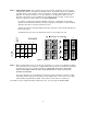
Figure 3 - Dip Switch Detail
4