
Manual


GENERAL TECHNICAL DESCRIPTION
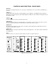
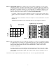
In the following illustration is a simplified block diagram of the LCA16 showing one amplifier channel. All channels
are identical.
The audio input of the LCA16 is an RF filtered, electronically balanced differential amplifier. An AUDIO THRU
output is provided so the audio signal can be "daisy chained" to other devices if required. A SIGNAL PRESENT
LED on the front panel indicates the presence of signal above -20dBv. The audio signal passes through the MAIN
LEVEL control before being distributed to the output channel amplifiers. Each output channel employs a dedicated
power amplifier. The amplifiers are fully protected from short circuits, thermal overloads or highly reactive loads.
Each amplifier is individually fused, so in the event of catastrophic failure of any single channel, no other channels
will be affected. Each output channel also includes a balanced line level output which is simultaneously available to
drive external amplifiers, or other audio equipment.
The logic input signal conditioning circuits are specially designed to accept a wide variety of logic signals, ranging
from relay contact closures to TTL logic levels. Each logic input passes through a time constant circuit with
hysteresis. This guarantees minimum "signal chopping" caused by changing attenuation during pauses in speech.
Photo-conductive opto-isolators are employed to switch the level of attenuation of the audio. These devices
eliminate the abrupt audible changes that occur when hard switching is used.
DIFFERENTIAL
L
O
G
I
C
I
N
P
U
T
S
Figure 1 - LCA16 Block Diagram
2
"A"
ATTENUATION
"B"
ATTENUATION
ATTENUATION
NO
ATTENUATION
"B"
ATTENUATION
"A"
ATTENUATION
NO
PWR
AMP
SPKR +
SPKR -
1
2
3
4
5
6
7
8
9
10
11
12
13
14
15
16 16
15
14
13
12
11
10
9
8
7
6
5
4
3
2
1
16 LINES
16 LINES 16 LINES
TO CHANNELS 2 THROUGH 16
MAIN LEVEL
L O G IC S IG N A L CO N D IT IO NIN G L O G IC S IG N A L CO NDIT IO N IN G
LINE OUT -
LINE OUT +
GROUND
BALANCED
LINE DRIVER
ATTENUATION
SELECT LOGIC
AND
LED DRIVERS
"A"
ATTENUATION
"B"
SELECT SWITCHES
ATTENUATION
SELECT SWITCHES
FRONT
PANEL
LEDs
CH. 1
TO CHANNELS 2 THROUGH 16
AUDIO
BALANCED
INPUT
AUDIO
THROUGH
OUTPUT
INPUT
AMPLIFIER
SIGNAL
PRESENT