
Manual

INSTALLATION
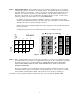
The LCA16 is designed to be mounted in a standard 19-inch equipment or cabinet. Adequate ventilation must be
provided which can normally be accomplished by leaving at least two open rack spaces (3 1/2 inches) above and below
the unit. Generally, the LCA16 should be positioned such that the intake air (from the bottom of the unit) is the coolest
available in the rack. If there are fans in the rack for cooling, optimum placement will be determined by the fan position.
INTERCONNECTIONS
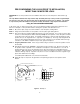
Refer to your LCA16 SYSTEM WORKSHEET to see which microphone is connected to each LOGIC INPUT, and
which speaker is connected to which output channel. Your room sketch will also be helpful. Number each
speaker and microphone and tag the wire pairs. Doing this prior to making any interconnections will save a
great deal of time during the initial setup. It is not necessary to install microphones and speakers in any
particular order.
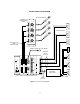
Audio Connection from Mixer / Signal Processor
Electrical connection to the AUDIO INPUT is made using a standard 3-pin XLR type connector. Pin 2 is audio "hot" (+),
pin 3 is audio "cold" (-), and pin 1 is ground (shield). If an unbalanced source is used for audio input, connect the
source ground to pins 1 and 3 at the LCA16, and source "hot" to pin 2. The use of a two-wire plus shield cable is
recommended, with the shield left unconnected at the source end and connected to signal ground at the LCA16 end
regardless of whether the source is balanced or unbalanced.
Logic Connections From Mixer
Electrical connection to the LOGIC INPUTS is made using stripped and tinned insulated hookup wire, 18 to 24 gauge. If
connecting to Lectrosonics’ AP4 Modular Audio Processor modules, simply connect the LOGIC OUT (+) of the AP4 to
the LOGIC INPUT (+) of the LCA16, and the LOGIC OUT (-) of the AP4 to the LOGIC INPUT (-) of the LCA16. If
multiple microphones are assigned to the same logic input, the logic connections may be connected in parallel.
If connection is being made to relay contacts, the polarity of the connection is unimportant. When connecting to the logic
outputs of other manufactures’ equipment, treat the LOGIC INPUT (-) on the LCA16 as "ground" and the LOGIC INPUT
(+) on the LCA16 as "signal" or "hot". Internally, the LOGIC INPUT (+) on the LCA16 is connected through 100k Ohm
to +5 Volts, so any logic output or other contact system which is interfaced to the LCA16 must be capable of sinking 50
microamps of continuous current. The LOGIC INPUTS of the LCA16 are active low.
Speaker Connections
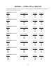
Electrical connections to the SPKR OUT terminals are made using any two wire cable of 22 gauge or larger. Refer to
the table in Appendix 1 for power loss vs cable distance data. The best practice is to tin the leads before insertion into
the terminal blocks to eliminate wire "whiskers" that might cause intermittent connections. The SPKR OUT terminals
drive low impedance loads (4 Ohms and above) directly, making a matching transformer at the speaker unnecessary.
The SPKR OUT + output terminal is in phase with pin 2 of AUDIO INPUT. The SPKR OUT - terminal is connected to
system ground. Neither of the output terminals should be connected to any other grounds (e.g. building grounds, cold
water grounds, etc.) or to any source of voltage. The only connections that should be made are to the speaker itself.
Line Out to Recorder or External Amplifier
Electrical connections to the LINE OUT terminals can be made in one of two ways, depending on whether a balanced or
unbalanced input is to be driven. In both cases a two-wire plus shield type of cable should be used. For driving a
balanced input, LINE OUT + connects to the signal "hot" (pin 2 on a standard XLR 3-pin connector), and LINE OUT -
connects to the signal "cold" (pin 3 on a standard XLR 3-pin connector). LINE OUT is connected to the shield of
the cable. It is not necessary to connect the shield to anything at the other end of the cable. The connection at the
LCA16 end is sufficient for shielding.
With a balanced system, there is no need to connect the grounds together. An additional benefit of this is that the
possibility of ground loops will be eliminated. For driving an unbalanced input, LINE OUT + is connected to the "signal"
terminal of the input to be driven, and the LINE OUT is connected to the "ground" terminal of the input. Note that
both "signal" and "ground" should be carried on the two wires of the cable. The shield should be connected to LINE
OUT on the LCA16 end and left unconnected on the other end.
10