LCA16 LOGIC CONTROLLED AMPLIFIER* OPERATING INSTRUCTIONS and trouble-shooting guide LECTROSONICS, INC.
INTRODUCTION Thank you for selecting the Lectrosonics LCA16 Logic Controlled Amplifier. The LCA16 is a modular multi-channel amplifier designed to minimize feedback and audio regeneration problems in conference room sound installations using distributed speaker systems. The speakers may be wall mounted, ceiling mounted, table mounted or any combination thereof. For proper operation, the automatic mixer must have logic signal outputs which indicate individual microphone activity.
GENERAL TECHNICAL DESCRIPTION In the following illustration is a simplified block diagram of the LCA16 showing one amplifier channel. All channels are identical. The audio input of the LCA16 is an RF filtered, electronically balanced differential amplifier. An AUDIO THRU output is provided so the audio signal can be "daisy chained" to other devices if required. A SIGNAL PRESENT LED on the front panel indicates the presence of signal above -20dBv.
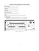
CONTROLS AND FUNCTIONS - FRONT PANEL POWER SWITCH Controls the application of AC power to the LCA16. POWER LED Indicates the presence of AC power to the LCA16. MAIN LEVEL Controls the overall output level of the sound system. SIGNAL PRESENT LED Indicates the presence of audio signal to the LCA16. ON LED (Channels 1-16) Indicates the output channel is in the "on" state (not attenuated). ATTENUATION LEDS A LED: (Channels 1-16) Indicates the output channel is at the "A" attenuation level.
ATTENUATION DIP SWITCHES (located behind front panel cover) These switches are used to programs which microphone (or microphones) connected to the 16 LOGIC INPUTS will trigger the "A" and "B" attenuation levels for each of the 16 output channels. Four banks of switches (eight switches per bank) are allocated to each channel. Two of the switch banks (16 switches) trigger the "A" attenuation level, the other two switch banks trigger the "B" attenuation level.
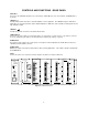
CONTROLS AND FUNCTIONS - REAR PANEL SPKR OUT Connects to the individual speakers in the sound system. SPKR OUT (+) is the "hot" terminal, and SPKR OUT (-) is ground. LINE OUT +/ Provides balanced line level drive to external amplifiers or other equipment. The LINE OUT signal is attenuated identically to its associated speaker output. Output impedance is 600 ohms, and is suitable for driving both low and high impedance inputs. LINE OUT Provides the ground connection for the balanced line driver.
PRE-CONFIGURING THE LCA16 PRIOR TO INSTALLATION, 16 or FEWER MICS PER LCA16 This procedure should be performed prior to installation. The LCA16 SYSTEM WORKSHEET (Appendix 2) will assist you in setting up the LCA16 before going on site. While the actual setup is quite simple, it is recommended that you use this worksheet, especially if this is your first installation using the LCA16 Logic Controlled Amplifier.
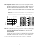
STEP 5 - Setting the DIP switches Upon completion of the chart you will have a grid which can now be used for setting the DIP switches on the LCA16. See Example 2 below. Each speaker output on the LCA16 has a set of dip switches on the front panel. There are two banks of 16 switches aligned vertically above a set of LED indicators. The left bank of switches is for "A" level attenuation. The right bank of switches is for "B" attenuation.
PRE-CONFIGURING THE LCA16 PRIOR TO INSTALLATION, MORE THAN 16 MICS PER LCA16 PROCEDURE 2 - Use this procedure for those installations where there are more microphone channels than logic inputs. The only difference between this setup and the setup described previously is that you have assigned multiple microphones to the same logic input because they are affected by the same group of speakers.
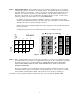
STEP 5 - Setting the DIP switches Upon completion of the chart you will have a grid which can now be used for setting the DIP switches on the LCA16. See Example 4 below. Each speaker output on the LCA16 has a set of DIP switches on the front panel. There are two banks of 16 switches aligned vertically above each LED bank. The left bank of switches is for "A" level attenuation. The right bank of switches is for "B" attenuation. DIP switches are set to the ON position by depressing them to the right.
INSTALLATION The LCA16 is designed to be mounted in a standard 19-inch equipment or cabinet. Adequate ventilation must be provided which can normally be accomplished by leaving at least two open rack spaces (3 1/2 inches) above and below the unit. Generally, the LCA16 should be positioned such that the intake air (from the bottom of the unit) is the coolest available in the rack. If there are fans in the rack for cooling, optimum placement will be determined by the fan position.
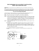
INTERCONNECTION DIAGRAM TO M ICRO P HO NE S AUT OMAT IC M IC R OPH ON E M IX ER MIC INP UT 1 SND RTN GND +D C - DC L OGIC OU TP U T S MIC INP UT 2 SND RTN GND + L O UDS P E A K E RS - L O G I C O UT P UT S MIC INP UT 3 S ND RTN GND + - L O G I C O UT P UT S MIC IN PUT 4 SND RTN GND + - TWIST ED PAIR LOGIC C ON NECT ION S L O G I C O UT P UT S AUT O M ATIC M I CRO P HO N E PR EAM P FROM AUDIO OUTPUT OF MIXER SPEAKER LEVEL O UTP UT S SER NO + - 9 1 SP KROUT + SP KROUT - + 13 LISTED +
ATTENUATION SETTINGS AND SPEAKER SYSTEM ADJUSTMENTS The steps and procedures in this section should be followed only after all wiring and audio connections have been completed, and the system components have been installed. It is also necessary to complete the worksheet for speaker attenuation and the pre-configuration instructions for the LCA16 before attempting the adjustments in this section.
SPECIFICATIONS Audio Input: Connectors: Impedance: Max Input Level: 3-pin female XLR, electronically balanced and RF filtered 20K Ohms balanced, 10K Ohms unbalanced +8dBv Thru Output: Connectors: 3-pin male XLR, parallel with Audio Input Logic Input: Connectors: Impedance: Terminal Strip 100K Ohms in parallel with 2.
SERVICE AND REPAIR If your system malfunctions, you should attempt to correct or isolate the trouble before concluding that the equipment needs repair. Make sure you have followed the setup procedure and operating instructions. Check out the inter connecting cords and then go through the TROUBLE SHOOTING section in the manual We strongly recommend that you do not try to repair the equipment yourself and do not have the local repair shop attempt anything other than the simplest repair.
APPENDIX 1 - POWER LOSS vs CABLE RUN The table below indicates power loss vs cable run for various wire gauges. Nominal output power for the LCA16 is 5 watts at 4 ohms and 3 watts at 8 ohms. 22 AWG Wire, 4 ohm load Distance 25ft. 50ft. 100ft. 250ft. Total Power Available 4.8W 4.5W 4.0W 3.1W Load Power 4.5W 4.0W 3.2W 1.9W Wire Loss .3W .5W .8W 1.2W 18 AWG Wire, 4 ohm load Distance 25ft. 50ft. 100ft. 250ft. Total Power Available 4.9W 4.7W 4.4W 3.6W Load Power 4.7W 4.3W 3.7W 2.6W Wire Loss .2W .4W .
APPENDIX 2 - LCA16 SYSTEM WORKSHEET Assigned Mics DIPSWITCH SETTINGS SPEAKER 1 2 3 4 5 6 7 1 2 3 4 5 LOG IC INPUT 6 7 8 9 10 11 12 13 14 15 16 16 8 9 10 11 12 13 14 15 16
LIMITED ONE YEAR WARRANTY The equipment is warranted for one year from date of purchase against defects in materials or workmanship provided it was purchased from an authorized dealer. This warranty does not cover equipment which has been abused or damaged by careless handling or shipping. This warranty does not apply to used or demonstrator equipment. Should any defect develop, we will, at our option, repair or replace any defective parts without charge for either parts or labor.