INSTRUCTION MANUAL IFBT4-VHF Synthesized VHF IFB Transmitter Featuring Digital Hybrid Wireless® Technology U.S. Patent 7,225,135 Fill in for your records: Serial Number: Purchase Date: Rio Rancho, NM, USA www.lectrosonics.
IFBT4-VHF 2 LECTROSONICS, INC.
Synthesized VHF IFB Transmitter Table of Contents General Technical Description.............................................4 Introduction..........................................................................4 Audio Input Interface............................................................4 Digital Hybrid Wireless® Technology....................................5 Audio Signal Processing......................................................5 Pilot Tone Squelch System.....................................
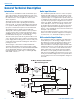
IFBT4-VHF General Technical Description Introduction Audio Input Interface This version of the IFB “base station” transmitter operates in the television broadcast band from 174 to 216 MHz (US TV channels 7 through 13). It will tune across the entire band, so clear frequencies can be found almost anywhere. The standard 3 pin XLR connector on the rear panel handles all audio inputs.
Synthesized VHF IFB Transmitter Digital Hybrid Wireless® Technology The design is based upon the patented Lectrosonics Digital Hybrid Wireless® system.* While at the time of the first release of the product, there is only a companion analog receiver, the Digital Hybrid Wireless system is included for compatibility with future products. Audio Signal Processing Lectrosonics IFB systems use a single band compandor and pre-emphasis/de-emphasis to reduce noise.
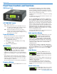
IFBT4-VHF Front Panel Controls and Functions IFBT4 Front Panel the Main window navigates to the Frequency window. The Frequency window displays the current operating frequency in MHz, as well as the standard Lectrosonics hex code. Also displayed is the UHF television channel to which the selected frequency belongs. In XMIT mode, it is not possible to change the operating frequency. In TUNE mode, the Up and Down buttons may be used to select a new frequency. OFF/TUNE/XMIT Switch OFF Turns the unit off.
Synthesized VHF IFB Transmitter of a 4 pole lowpass digital filter. The 50 Hz setting is the default, and should be used whenever wind noise, HVAC rumble, traffic noise or other low frequency sounds may degrade the quality of the audio. The 35 Hz setting may be used in the absence of adverse conditions, for a fuller bass response. Press MENU to return to the Setup window. COMPAT Setup Screen The COMPAT setup screen selects the current compatibility mode, for interoperation with various types of receivers.
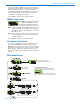
IFBT4-VHF Rear Panel Controls and Functions IFBT4 Rear Panel Input Configuration (Mode Switches) The MODE switches allow the IFBT4 to accommodate a variety of input source levels by changing the input sensitivity and the pin functions of the input XLR jack. Marked on the rear panel are the most common settings. Each setting is detailed below. Switches 1 and 2 adjust the XLR pin functions while switches 3 and 4 adjust the input sensitivity.
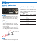
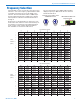
Synthesized VHF IFB Transmitter Frequency Selection The R1A-VHF receiver provides two 16-position rotary switches to select the frequency, adjusted with a small screwdriver inserted in the slot in the middle of the switches. The left-hand switch makes 2.8 MHz steps and the right-hand switch in 175 kHz steps, with the switch positions marked in hexadecimal numerals 0 through F.
IFBT4-VHF Installation and Operation 1) The IFBT4 transmitter is shipped with pin 1 of the XLR input connector tied directly to ground. If a floating input is desired, a Ground Lift Jumper is provided. This jumper is located inside the unit on the PC board near the rear panel XLR jack. For floating input, open the unit and move the Ground Lift Jumper to the outermost contacts.
Synthesized VHF IFB Transmitter Accessories CH20 Power supply for IFB base transmitters with locking LZR power jacks; 110 VAC input, 12 VDC regulated output; 400 mA max. CH20 A170AC VHF straight whip antenna; right angle BNC connector ARG15 A 15 foot antenna cable of standard RG-58 coax cable with BNC connectors at each end. Loss of 1 to 2 dB with 0.25” diameter. ARG15 ARG25 ARG50 ARG100 ARG25/ARG50/ARG100 An antenna cable of Belden 9913F low-loss coax cable with BNC connectors at each end.
IFBT4-VHF Troubleshooting NOTE: Always ensure that the COMPAT (compatibility) setting is the same on both transmitter and receiver. A variety of different symptoms will occur if the settings do not match. Symptom: Possible Cause: Display Dead 1) 2) No Transmitter Modulation External power supply disconnected or inadequate. The External DC power input is protected by an auto-reset polyfuse. Disconnect power and wait about 1 minute for the fuse to reset.
Synthesized VHF IFB Transmitter Specifications Operating Frequencies (MHz): Available Frequencies: Channel Spacing: RF Power Output: Frequency Stability: Temperature Stability: Channel Selection: Compatibility Modes (2) Pilot Tone: Modulation: Audio Frequency Response: Rolloff: Audio Compressor: Input Limiter Range: Output Impedance: Audio Input Levels: Audio Input Config: Audio Input Impedance: Gain Control Range: Audio Input Jack: 174.100 to 215.
IFBT4-VHF Service and Repair If your system malfunctions, you should attempt to correct or isolate the trouble before concluding that the equipment needs repair. Make sure you have followed the setup procedure and operating instructions. Check the interconnecting cables and then go through the Troubleshooting section in this manual. We strongly recommend that you do not try to repair the equipment yourself and do not have the local repair shop attempt anything other than the simplest repair.
Synthesized VHF IFB Transmitter Rio Rancho, NM 15
LIMITED ONE YEAR WARRANTY The equipment is warranted for one year from date of purchase against defects in materials or workmanship provided it was purchased from an authorized dealer. This warranty does not cover equipment which has been abused or damaged by careless handling or shipping. This warranty does not apply to used or demonstrator equipment. Should any defect develop, Lectrosonics, Inc. will, at our option, repair or replace any defective parts without charge for either parts or labor.