
User's Manual


Multi-Frequency IFB Transmitter
Rio Rancho, NM
13
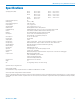
Specifi cations
Operating Frequencies (MHz): Block 21 537.600 - 563.100 Block 25 640.000 - 665.500
Block 22 563.200 - 588.700 Block 26 665.600 - 691.100
Block 23 588.800 - 607.900 Block 27 691.200 - 716.700
614.100 - 614.300 Block 28 716.800 - 742.300
Block 24 614.400 - 639.900 Block 29 742.400 - 767.900
Block 944 944.100 – 951.9
Frequencies (Channels per block): 256
Channel Spacing: 100 kHz (0.1 MHz)
Spurious & Harmonic Suppression: 37 dBc above 1 GHz
Frequency Stability: ±.001% (10 ppm) @ 25° C
Temperature Stability: ±.001% (10 ppm) from -30° C to +50° C
Channel Selection: Momentary pushbutton switches, TUNE Up and Down
Compatibility Modes (6) Digital Hybrid Wireless(tm) (400 Series), 100 Series, 200 Series, Mode 3, Mode 6, and IFB
Pilot Tone: 29.997 kHz IFB & 100 MODE, 32.765kHz 200 MODE, 400 MODE step selected
Modulation: FM, ±20 kHz deviation IFB & 100 MODE, ±75kHz 200 & 400 MODE
Audio Response: 100 Hz to 10 kHz, ±1 dB, -3dB, IFB MODE system response
50Hz to 20kHz ±1dB , 200 & 400 MODE system response
Audio Compressor: 2 to 1 IFB, 100, and 200 Mode
RF Power Output: 250 mw (nominal)
Output Impedance: 50 ohms
Audio Input Levels: 0 dBu for Line, RTS1 & RTS2. -10 dBu for Clear Com, and -42 dBu for mic dry inputs, +/-50Vdc max,
Audio Input Confi g: Balanced and Unbalanced, rear panel selectable for Line, Mic. RTS 1, RTS 2, and Clear Comm
Audio Input Impedance: Greater than 2 K balanced, greater than 1 K unbalanced at any gain setting
Gain Control Range: ±20 dB, Menu selectable
Audio Input Jack: Standard XLR female connector
Input Power: 12 to 14 VDC typical, 200 ma. max.; Max. Input Range 6 to 18 VDC
Power Input Jack: Coax type, locking LZR RL26AE
Indicators: Backlit Liquid Crystal Display. Displays modulation meter, frequencies, modes, rolloff, audio level, and tuning groups.
Front panel controls: MENU momentary pushbutton switch
Power OFF-TUNE-XMIT, 3 position slide switch
Select Up momentary pushbutton switch
Select down momentary pushbutton switch
Rear panel controls: Input Mode Select, 4 section DIP switch
Weight: 9 oz.
Size: 5.25” long (including connectors) x 3.25” wide x 1.25” high
Specifi cations subject to change without notice.
Emission designator: 180KF3E
The T4 IFB transmitter is FCC type accepted under Part 74: 470 - 608MHz, 614 - 806MHz and 944.1 – 951.9MHz.
The FCC requires that the following statement be included in this manual:
This device complies with FCC radiation exposure limits as set forth for an uncontrolled environment. This device should be installed and operated so that its antenna(s) are not co-located or operating in
conjunction with any other antenna or transmitter. A separation distance of at least 20cm (8 inches) must be maintained to comply with the FCC Radio Frequency Maximum Permissible Exposure (MPE)
requirements.