Quick Start Guide IFBT4 IFB Transmitter U.S. Patent 7,225,135 Fill in for your records: Serial Number: This guide is intended to assist with initial setup and operation of your Lectrosonics product. Purchase Date: For a detailed user manual, download the most current version at: www.lectrosonics.
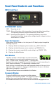
Front Panel Controls and Functions IFBT4 Front Panel OFF/TUNE/XMIT Switch OFF Turns the unit off. TUNE Allows all functions of the transmitter to be set up, without transmitting. The operating frequency may be selected only in this mode. XMIT Normal operating position. The operating frequency may not be changed in this mode, though other settings may be changed, so long as the unit isn’t “Locked.
switches. Also displayed is the UHF television channel to which the selected frequency belongs. In XMIT mode, it is not possible to change the operating frequency. In TUNE mode, the Up and Down buttons may be used to select a new frequency. If the TUNING mode is set to NORMAL, the Up and Down buttons navigate in single channel increments, and MENU+Up and MENU+Down move 16 channels at a time.
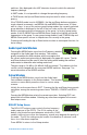
COMPAT Setup Screen The COMPAT setup screen selects the current compatibility mode, for interoperation with various types of receivers. The available modes are: IFB - Lectrosonics IFB compatibility mode. This is the default setting and is the appropriate setting to use with the Lectrosonics IFBR1A or a compatible IFB receiver. 400 - Lectrosonics 400 Series. This mode offers the best audio quality and is recommended if your receiver supports it. 100 - Lectrosonics 100 Series compatibility mode.
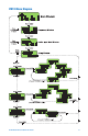
IFBT4 Menu Diagram www.lectrosonics.
Frequency Window Behavior, based on TUNING mode selections If NORMAL tuning mode is selected, the Up and Down buttons select the operating frequency in single channel (100 kHz) increments and the MENU+Up and MENU+Down shortcuts tune in 16 channel (1.6 MHz) increments. There are two classes of group tuning: factory preset groups (Grp A through D) and user programmable frequency groups (Grp U and V).
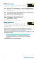
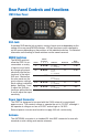
Rear Panel Controls and Functions IFBT4 Rear Panel XLR Jack A standard XLR female jack accepts a variety of input sources depending on the setting of the rear panel MODE switches. XLR pin functions can be changed to suit the source depending on the positions of the individual switches. For detailed information on the setting of these switches see the owner’s manual.
FCC Notices: Emission designator: 180KF3E The IFBT4 transmitter is FCC type accepted under Part 74: 470 - 608MHz, 614 - 806MHz and 944.1 – 951.9MHz. This device complies with FCC radiation exposure limits as set forth for an uncontrolled environment. This device should be installed and operated so that its antenna(s) are not co-located or operating in conjunction with any other antenna or transmitter.