
User's Manual


Digital Hybrid
™
Plug-On Transmitter
Rio Rancho, NM
7
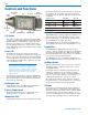
Setup with the LCD
LCD screens and membrane switches are used to set
the operating frequency, adjust the audio input level,
select the Compatibility Mode, turn power on and off
and to lock out the control panel.
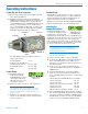
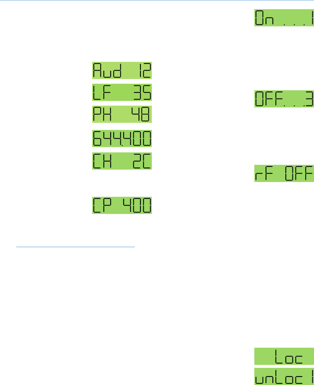
Audio Screen
The Audio screen is used
to adjust input gain and low
frequency roll-off, and to turn
phantom power on and off. Re-
peatedly pressing the AUDIO
button selects the setting. Press
and hold the AUDIO button and
use the Up and Down arrows to
adjust the value.
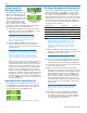
Frequency Screen
The Frequency Screen dis-
plays the operating frequency
in MHz or as a two-digit
hexadecimal number that cor-
responds to the equivalent
Lectrosonics Frequency Switch
Setting. Pressing the FREQ button toggles between the
two displays.
Compatibility Mode
Screen
Holding down the Up arrow button while powering up
the SM opens the Compatibility Mode screen. By using
the Up or Down arrow buttons, the user can select one
of six compatibility modes:
Note: RF transmission is prevented while selecting
Compatibility Modes. Also, the HM exits the
Compatibility Mode screen to Standby Mode.
• 400-Thisisthefactorydefaultsettingandworkswith
all Lectrosonics 400 Series Digital Hybrid Wireless
™
receivers, including the Venue. This mode offers the
best audio quality.
• 200-ThismodeworkswithallLectrosonics200
Series compatible receivers.
• 100-ThismodeworkswithallLectrosonics100
Series compatible receivers.
• 3-(Mode3)Thismodeworkswithanumberof
non-Lectrosonics analog receivers. Contact the
company for a list of compatible receivers.
• IFB-ThismodeworkswithallLectrosonicsIFB
compatible receivers.
• 6-(Mode6)Thismodeworkswithanumberof
non-Lectrosonics analog receivers. Contact the
company for a list of compatible receivers.
While in the compatibility mode screen, pressing either
the AUDIO or FREQ button exits to standby mode. To
power off from the compatibility mode screen, press
and hold AUDIO and FREQ together.
Turning the Power On
With the power turned off,
simultaneously pressing and
holding the AUDIO and FREQ
buttons displays a timer with
numerals on the right. The numerals count up from one
and the boot sequence begins when the count reaches
three. “LECtro” is displayed as the boot sequence be-
gins. If either button is release prior to the screen reach-
ing numeral three, the unit will enter the Standby Mode
with no RF output (see Standby Mode below).
Turning the Power Off
With the unit turned on, simul-
taneously holding the AUDIO
and FREQ buttons starts a
countdown timer with numerals
on the right. The screen counts down from three and
the transmitter turns off when it reaches zero. Releas-
ing either button prior to the Power Off Timer screen
indicating zero returns the unit to normal operation and
displays the previous screen.
Entering the
Standby Mode
With the power turned off,
pressing the AUDIO and FREQ
buttons for about one second places the unit in Standby
Mode. In this mode the RF output is turned off so all
setup adjustments can be made without interfering
with other systems operating in the same location. The
screen displays “rf OFF” to remind the user that the unit
is not transmitting.
Holding the FREQ button in Standby Mode displays the
current operating frequency of the transmitter. The op-
erating frequency can be changed by holding the FREQ
button and pressing either the Up or Down button.
Release the FREQ button, then press and hold it again
to toggle the display between frequency in MHz and the
hex code corresponding to the equivalent Lectrosonics
Frequency Switch Setting.
Holding the AUDIO button in Standby Mode displays
the current audio input level setting. This level can be
changed by holding the AUDIO button and pressing
either the Up or Down button.
Quickly pressing both the FREQ and AUDIO buttons
simultaneiously when the unit is in Standby Mode pow-
ers off the transmitter.
Lock/Unlock Screen
Simultaneously pressing and
holding both the Up and Down
arrow buttons during normal
operation starts the Lock timer.
The timer starts at three and
counts down to zero. When the timer reaches zero, the
transmitter’s controls are locked.
Initial Power On
Timer Screen
Initial Power Off
imer Screen
Standby Screen