
User's Manual
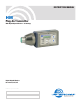


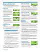
HM
LECTROSONICS, INC.
6
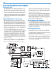
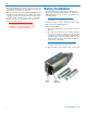
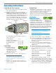
Controls and Functions
LCD Screen
The LCD is a numeric-type Liquid Crystal Display with
several screens that allow settings to be made with the
AUDIO, FREQ, UP and DOWN to configure the trans-
mitter. Turn on and turn off countdowns appear in the
LCD allowing the transmitter to be turned on for adjust-
ments without the output stage enabled, and to prevent
accidental turn off.
Power LED
The PWR LED glows green when the batteries are
good. The color changes to red when there is about 30
minutes of operation left with the recommended lithium
batteries. Alkaline batteries will have about 20 minutes
of life left. When the LED begins to blink red, there are
only a few minutes of life.
Note: NiMH batteries will give little or no warning
when depleted. If you wish to use NiMH batteries
in the HM, we recommend trying fully charged
batteries in the unit, noting the length of time that
the batteries will run the unit and then using the
battery timer feature available on most Digital
Hybrid receivers.
A weak battery will sometimes cause the PWR LED to
glow green immediately after being put in the unit, but
will soon discharge to the point where the LED will go
red or shut off completely.
Audio Input Jack
The XLR input jack on the HM Series transmitters ac-
commodates most hand-held microphones.
Battery Compartment
The Battery Compartment Cover Plate slides open,
allowing access to the battery compartment.
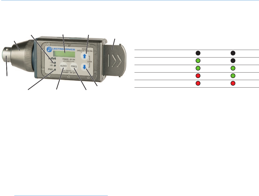
Modulation LEDs
The Modulation LEDs provide a visual indication of the
input audio signal level from the microphone. These two
bicolor LEDs can glow either red or green to indicate
modulation levels. 0 dB in the table below indicates full
modulation.
Signal Level -20 LED -10 LED
Less than -20 dB Off Off
-20 dB to -10 dB
Green Off
-10 dB to +0 dB Green Green
+0 dB to +10 dB Red Green
Greater than +10 db
Red Red
Audio Button
The AUDIO button is used to display the audio level set-
ting, low frequency roll-off and phantom power mode.
Repeated pressings cycle through the settings and the
UP and DOWN arrows adjust the values.
The AUDIO button is also used with the FREQ button to
enter standby mode and to power the transmitter on or off.
Freq Button
The FREQ Button displays the selected operating
frequency and also toggles the LCD between displaying
the actual operating frequency in MHz and a two-digit
hexadecimal number that corresponds to the equivalent
Lectrosonics Frequency Switch Setting.
The FREQ button is also used with the AUDIO button to
enter standby mode and to power the transmitter on or off.
Up/Down Arrows
The Up and Down arrow buttons are used to select the
operating frequency, adjust the audio level, or set the
Compatibility Mode.
Pressing both arrows simultaneously enters the lock
countdown. Holding the two arrow buttons until the
countdown completes locks the control panel buttons so
they can only be used to display current settings. “Loc”
is displayed to indicate the controls are locked.
Once locked, the buttons can be unlocked only by re-
moving the battery, or via the RM remote control (if this
function was enabled in the transmitter setup).
Antenna
An antenna is formed between the housing and the at-
tached microphone, operating much like a dipole type.
At UHF frequencies the length of the housing is similar
to 1/4 wavelength of the operating frequency, so the
antenna is surprisingly efficient, which helps extend the
operating range and suppress noise and interference.
Battery
Compartment
Cover
XLR Input
Jack
AUDIO Button
LCD
Input
Coupler
FREQ Button
Modulation
LEDs
PWR LED
UP Arrow
DOWN Arrow