
User's Manual


Digital Hybrid
™
Plug-On Transmitter
Rio Rancho, NM
5
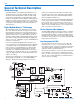
Input Limiter
A DSP-controlled analog audio limiter is employed before
the analog-to-digital (A-D) converter. The limiter has a range
of more than 30 dB for excellent overload protection. A dual
release envelope makes the limiter acoustically transparent
while maintaining low distortion. It can be thought of as two
limiters in series, a fast attack and release limiter followed by
a slow attack and release limiter. The limiter recovers quickly
from brief transients, with no audible side effects, and also
recovers slowly from sustained high levels, to keep audio
distortion low and while preserving short term dynamics.
Signal Encoding and Pilot Tone
In addition to controlling the limiter, the DSP also en-
codes the digitized audio from the A-D converter and
adds an ultrasonic pilot tone to control the receiver’s
squelch. A pilot tone squelch system provides a reliable
method of keeping a receiver output muted (squelched)
even in the presence of significant interference. When
the system is operating in the hybrid mode, a differ-
ent pilot tone frequency is generated for each carrier
frequency to prevent inadvertent squelch problems and
simplify multi-channel coordination.
Microprocessor and DSP
A microprocessor monitors user command inputs from
the control panel buttons and numerous other internal
signals. It works intimately with the DSP to ensure the
audio is encoded according to the selected Compatibil-
ity Mode and that the correct pilot tone is added to the
encoded signal.
Compatibility Modes
The HM transmitter was designed to operate with
Lectrosonics Digital Hybrid receivers and will yield the
best performance when doing so. However, due to the
flexibility of digital signal processing, the transmitters
can also operate in various compatibility modes for use
with Lectrosonics 200 Series, Lectrosonics 100 Series,
IFB and certain non-Lectrosonics receivers. Contact
the Lectrosonics sales department for a complete list of
compatible non-Lectrosonics receivers.
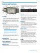
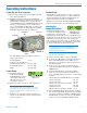
Control Panel
The control panel includes four membrane switches and
an LCD screen to adjust the operational settings. Multi-
color LEDs are used to indicate audio signal levels for
accurate gain adjustment and for battery status.
Wide-Band Deviation
±75 kHz deviation improves the signal to noise ratio and
audio dynamic range of a wireless system dramatically,
compared to other designs that use ±30 kHz to 40 kHz
deviation. Wide deviation combined with a high powered
transmitters makes a significant improvement in signal
to noise ratio and operating range.
Battery Options and Operating Time
Switching power supplies convert battery voltages to
operate various circuit stages with maximum efficiency.
With the variety of alkaline, lithium and rechargeable
NiMH batteries available today in the AA format, there
are many choices to maximize operating time or mini-
mize cost as needed for any application.
Frequency Blocks
Lectrosonics established a “block” numbering system
years ago to organize the range of frequencies avail-
able from the low 500 MHz band to the upper 700
MHz band. Each block includes 256 frequencies in 100
kHz increments. The block number is part of a simple
formula to derive the frequency. The block number is
multiplied by 25.6 to produce the lowest frequency in
the block. For example, block 27 x 25.6 = 691.200.
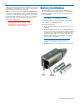
Circulator/Isolator
The RF output circuit includes a one way circulator/isolator
using a magnetically polarized ferrite. This device greatly
reduces the RF intermodulation produced when multiple
transmitters are used in close proximity to one another
(several feet apart). The isolator also provides additional
RF output stage protection.