
Instruction Manual

Wideband Digital Hybrid
®
Plug-On Transmitter
Rio Rancho, NM
11
• 48 Volts for microphones that do in fact require a
supply greater than 18 Volts. (See following for a
discussion of why 42 and not a “true” 48 Volts.)
For longest battery life use the minimum phantom volt-
age necessary for the microphone. Many stage micro-
phones regulate the 48 Volts down to 10 Volts internally
anyway, so you might as well use the 15 Volt setting and
save some battery power. If you are not using a micro-
phone for the input device, or are using a microphone
that does not require phantom power, turn the phantom
power off.
Phantom power should only be used with a fully float-
ing, balanced device such as most microphones with
a 3-pin XLR connector. If you use the phantom power
with an unbalanced device or if pins 2 or 3 are DC con-
nected to ground, then you will draw maximum current
from the power supply. The HM is fully protected against
such shorts but the batteries will be drained at twice the
normal rate.
The transmitter can supply 4 mA at 42 Volts, 8 mA at 15
Volts, and 8 mA at 5 Volts. The 42 Volts setting actually
supplies the same voltage to a 48 Volt microphone as
the DIN standard arrangement due to a dynamic bias-
ing scheme that does not have as much voltage drop
as the DIN standard. The 48 Volt DIN standard arrange-
ment protects against shorts and high fault current with
high resistance in the power supply feeds to pins 2 and
3. This provides protection if the supply current is ac-
cidentally shorted to ground and also keeps the micro-
phone from being attenuated by the power supply.
The HMa improves on those functions and is able to
use less power from the battery by using constant
current sources and current limiters. With this dynamic
arrangement the HMa can also supply more than twice
the current of competing 48 Volt plug on units and pro-
vide four times the current for some very high end 15
Volt microphones.
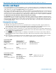
FREQ Button Settings
Press the FREQ button on the Control Panel to enter
this setup screen. The display will vary depending upon
which StepSize setting is selected. See Selecting Step
Size on page 9.
Note: The default display is in MHz. Pressing
the FREQ button again displays the operating
frequency as a two-digit hexadecimal number that
corresponds to legacy Lectrosonics products that
used two 16-position switches to set the frequency.
While holding the FREQ button, use the UP or DOWN
arrow buttons to change the frequency.
Note: The operating frequency displayed on the
LCD wraps as it reaches the upper or lower end of
its range.
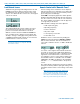
Block 470/19 Frequency Overlap
Frequencies 486.400 - 495.600 Overlap in Blocks 470 and 19
Block 470 and block 19 overlap each other in the
frequency range from 486.400 to 495.600 MHz. Since
block 470 starts at a lower frequency than block 19,
the hex codes (and pilot tones) will not match even
though the frequencies are the same in the overlap
zone. When using a transmitter on the A1 band
with a block 19 receiver, be sure the transmitter is
set to block 19 and check the hex code on the re-
ceiver to make sure it matches the transmitter.
Call the factory for further questions on this issue.
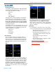
Set Up in 100kHz Step Size
Frequency displayed as
two-digit hexadecimal
number
Frequency displayed
in MHz
The operating frequency can
be displayed either in MHz
or as a two-digit hexadeci-
mal number. The example
of the two-digit display
shown here indicates CH
(channel) and 2C as the
frequency.
The frequency can be set
with the unit in standby
mode or when powered up
for normal operation.
Set Up in 25kHz Step Size
Frequency expressed in MHz
The hexadecimal display in the 25 kHz mode will
appear with a decimal suffix to indicate the 25 kHz
steps.
Standard
frequency
block (20)
Frequency
in hex
code (F6)
Offset in
MHz (.25)
Frequency in hex
Examples:
475.875 MHz
490.225 MHz
487.650 MHz
509.200 MHz