
User's Manual

HMa
LECTROSONICS, INC.
10
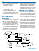
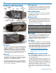
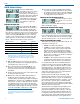
AUDIO Button Settings
Press the AUDIO button
repeatedly to select the setting.
Each time the button is re-
leased, the screen will switch to
the next setting. Press and hold
the button when the desired
setting appears on the screen,
then use the UP and DOWN
arrow buttons to adjust the
setting.
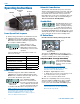
Adjusting the Input Gain
The control panel Modulation
LEDs indicate the modulation
level and limiter activity. This
gain adjustment matches the transmitter gain with the
microphone’s output level, the user’s voice level and the
position of the microphone. Once set, the transmitter’s
audio level setting should not be used to control the
volume of your sound system or recorder levels. The
audio input level can be set with the unit in Standby
Mode or while powered up in normal operation.
Signal Level -20 LED -10 LED
Less than -20 dB Off Off
-20 dB to -10 dB Green Off
-10 dB to +0 dB Green Green
+0 dB to +10 dB Red Green
Greater than +10 dB Red Red
Note: Voice levels vary significantly between
different people. If several different people will be
using the transmitter and there is not time to make
the adjustment for each individual, adjust it for the
loudest voice.
1) With the HMa powered off, insert the microphone
plug into the XLR Input Jack, aligning the pins and
ensuring that the connector locks.
2) Place the transmitter in the Standby Mode, or if
the unit is to be powered up and adjusted, mute
the main sound system prior to powering up the
transmitter.
3) Position the microphone in the location where it will
be used in actual operation.
4) Observe the audio level LEDs while speaking or
singing into the microphone at the same voice
level that will be used during use. While holding the
AUDIO button, press the UP or DOWN arrows until
the both the -20 and -10 LEDs glow green, with the
-20 LED flickering red on louder peaks. This will
optimize the signal to noise ratio of the system with
full modulation and adequate headroom to prevent
overload and audible compression of signal peaks.
Note: Setting the audio level too high reduces
the dynamic range of the audio signal. Setting the
audio level too low may cause hiss and noise in
the audio.
5) If the unit was set up in Standby Mode, it will be
necessary to turn the transmitter off, then power it
up again in normal operation so the RF output will
be on. Then the other components in the sound or
recording system can be adjusted.
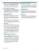
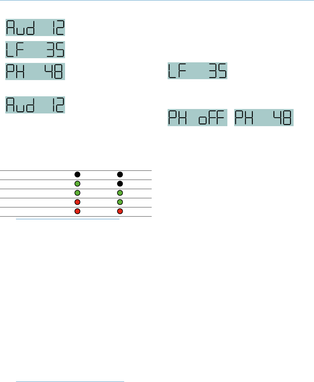
Adjusting the Low Frequency Roll-off
The roll-off frequency can be
set to 35, 50, 70, 100, 120 or
150 Hz.
This setting is often made while listening to the audio
while selecting the setting.
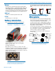
Selecting the Phantom Power Supply
The transmitter input jack can provide phantom power
for the attached microphone if needed, with voltages
at 5, 15 or 48. Phantom power will consume a slight
amount of battery power, so it can also be turned off.
About the Phantom Power Supply
Three phantom voltages are selectable from the con-
trol panel. The voltages are:
• 5 Volts for lavaliere microphones,
• 15 Volts for some professional mics requiring
high current and for many common stage mics
that will operate over a wide phantom Voltage
range of 12 to 48 Volts. With the proper adapter,
this position can also be used with T power micro-
phones. See our web site for details on finding or
making the proper adapter.
• 48 Volts for microphones that do in fact require
a supply greater than 18 Volts. (See below for a
discussion of why 42 and not a “true” 48 Volts.)
For longest battery life use the minimum phantom
voltage necessary for the microphone. Many stage
microphones regulate the 48 Volts down to 10 Volts
internally anyway, so you might as well use the 15
Volt setting and save some battery power. If you are
not using a microphone for the input device, or are
using a microphone that does not require phantom
power, turn the phantom power off.
Phantom power should only be used with a fully
floating, balanced device such as most microphones
with a 3-pin XLR connector. If you use the phantom
power with an unbalanced device or if pins 2 or 3 are
DC connected to ground, then you will draw maxi-
mum current from the power supply. The HM is fully
protected against such shorts but the batteries will be
drained at twice the normal rate.
The transmitter can supply 4 mA at 42 Volts, 8 mA
at 15 Volts, and 8 mA at 5 Volts. The 42 Volts set-
ting actually supplies the same voltage to a 48 Volt
microphone as the DIN standard arrangement due
to a dynamic biasing scheme that does not have as
much voltage drop as the DIN standard. The 48 Volt
DIN standard arrangement protects against shorts