INSTRUCTION MANUAL HH Handheld Transmitter Digital Hybrid Wireless® Technology US Patent 7.225.135 Fill in for your records: Serial Number: Purchase Date: Rio Rancho, NM, USA www.lectrosonics.
HH Table of Contents General Technical Description............................................. 3 Mic Capsules:........................................................................ 5 Mechanical Design................................................................ 5 Battery Installation................................................................ 6 Control Panel......................................................................... 6 Powering On......................................................
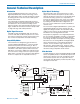
Hand Held Transmitter General Technical Description Introduction Digital Hybrid Technology The HH handheld transmitter uses state-of-the-art Digital Hybrid Wireless® wireless technology, selectable output power and a versatile microphone capsule mounting system to meet the needs of audio professionals and vocalists. All wireless links suffer from channel noise to some degree and all wireless microphone systems seek to minimize the impact of that noise on the desired signal.
HH Pilot Tone Squelch The benefit of the pilot tone squelch system is that the associated receiver will remain muted until it receives the pilot tone from the matching transmitter, even if a strong RF signal is present on the carrier frequency of the system. All Digital Hybrid transmitters use one of 256 different ultrasonic tones between 25 and 32 kHz to operate the receiver squelch.
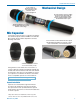
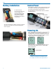
Hand Held Transmitter A mic capsule is threaded onto the body of the transmitter in the direction shown. Do not overtighten it. Mechanical Design The lower housing opens by rotating it in the direction shown. After the threads are disengaged, pull the housing downward until it engages the detent that holds it open. The threaded interface is a 1.25” opening with 28 threads per inch and three contact rings Mic Capsules: Lectrosonics offers two types of capsules.
HH Battery Installation To insert batteries, close the eject lever and insert the upper contacts first (closest to the mic capsule). Polarity is marked on the label in the bottom of the battery compartment. To remove the batteries, pull the eject lever outward. The battery tips will move outward, making them easier to grasp. Control Panel Six membrane switches on the control panel are used to set up the transmitter by navigating the menus on the LCD and selecting the desired values.
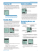
Hand Held Transmitter Powering Off Battery Condition Press and hold the Power Button (or the side button if it is configured for turning the power on and off) for several seconds and observe the countdown on the LCD. The countdown on the LCD will progress from 3 to 1 and the power will then be turned off. This can be done from any menu or screen. Powering Off . . . An icon on the Main Window indicates the remaining power of the transmitter batteries.
HH Gain Compat This setting is very important since it will determine the audio signal to noise ratio and dynamic range that the wireless system will deliver. Gain must be set according to the individual voice, the mic capsule in use and the handling technique of the user. LEDs in the control panel facilitate accurate gain adjustment. Gain Freq. Button Rolloff Gain -40 -20 25 0 IMPORTANT: See the section Input Gain Adjustment on page 10 for details. Freq. Freq 8A 628.
Hand Held Transmitter Phase The phase (polarity) of the audio can be inverted to match other microphone capsules as needed. TxPower Phase Backlgt Rf On? Phase Input Gain Adjustment The two bicolor Modulation LEDs (located at the bottom of the control panel) provide a visual indication of the audio signal level entering the transmitter. 5A Pos Neg 623.400 Backlgt -40 The LCD includes a backlight that illuminates the display for easier viewing in dim lighting conditions.
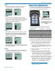
HH Side Button Functions Button NOTE: The Power and Cough functions were added starting with serial number 1001. Cough A special button (the Side Button) on the outside of the housing can be configured to provide a several different functions, or to be inoperative. Side Button Functions: • TalkBack • Power • Cough • Mute • (none) Button Mute The Side Button Setup Switch on the control panel opens a setup screen to set the Side Button function.
Hand Held Transmitter Mic Capsule Adjustments (EXPERT LEVEL ADJUSTMENT) Resonance tuned suspension HHVMC capsule These adjustments significantly alter the gain and tonal quality of the microphone, and are to be used only in special circumstances. Caution: Always make the final decision about sound quality with the windscreen in place. Remove the windscreen using the supplied wrench. Attenuator control EQ controls (HHVMC only) Align flats on the wrench with flats on the capsule.
HH Parts and Accessories #55008 - Blue Battery Caddy or #55009 - Clear Battery Caddy #13585 Mic Clip Screw on mic clip for standard mic stands with 5/8”-27 thread HHXTND Extender to for use with microphone flags commonly used in ENG for network or station ID to keep the flag from covering the side switch and LCD HH2SEN Adapter Adapts Sennheiser G2, G3 and 2000 Series microphone capsule heads to the HH transmitter.
Hand Held Transmitter Troubleshooting SYMPTOM POSSIBLE CAUSE HH WILL NOT POWER ON 1) Batteries are inserted backwards. 2) Batteries are dead, or too low to be used. HH MODULATION LEDs OFF 1) 2) 3) Audio Gain set too low. Battery is inserted backwards. Check LCD for power indication. Mic capsule is damaged or malfunctioning. Contact the factory for repair. HH MODULATION LEDs GOOD BUT NO SOUND 1) 2) 3) 4) Talkback function is engaged (release multi-function button). See p. 11.
HH Specifications Operating frequencies:† Block 470 470.100 - 495.600 Block 19 486.400 - 511.900 Block 20 512.000 - 537.500 Block 21 537.600 - 563.100 Block 22 563.200 - 588.700 Block 23 588.800 - 614.300 Block 24 614.400 - 639.900 Block 25 640.000 - 665.500 Block 26 665.600 - 691.
Hand Held Transmitter Service and Repair If your system malfunctions, you should attempt to correct or isolate the trouble before concluding that the equipment needs repair. Make sure you have followed the setup procedure and operating instructions. Check the interconnecting cables and then go through the Troubleshooting section in this manual. We strongly recommend that you do not try to repair the equipment yourself and do not have the local repair shop attempt anything other than the simplest repair.
LIMITED ONE YEAR WARRANTY The equipment is warranted for one year from date of purchase against defects in materials or workmanship provided it was purchased from an authorized dealer. This warranty does not cover equipment which has been abused or damaged by careless handling or shipping. This warranty does not apply to used or demonstrator equipment. Should any defect develop, Lectrosonics, Inc. will, at our option, repair or replace any defective parts without charge for either parts or labor.