DR185 RATIO DIVERSITY RECEIVER OPERATING INSTRUCTIONS and trouble-shooting guide LECTROSONICS, INC.
INTRODUCTION Thank you for selecting the Lectrosonics system. The DR185 represents over 70 years of combined experience in the design of RF and audio devices and sets new standards for RF performance and flexibility. This receiver utilizes a “maximal ratio combining” technique, providing a very effective type of diversity reception. This is the first high performance receiver on the market to utilize this technique to combine the outputs of two separate receivers without hard-switching.
Ratio Diversity Receiver GENERAL TECHNICAL DESCRIPTION The DR185 receiver consists of two independent receivers operating with common first and second oscillators. The audio outputs of the two receivers are mixed via a comparator circuit in a ratio controlled by sampling and comparing the signal to noise ratios in both receivers. High frequency noise is compared between the receivers and an elec tronic “panning” circuit mixes in a greater percentage of audio from the quieter receiver.
FRONT PANEL CONTROLS AND FUNCTIONS MODULATION INDICATORS Nine (9) LEDs indicate the audio level (modulation) of the incoming signal, which are typically used for proper adjust ment of the transmitter’s “MIC LEVEL” or “GAIN”. The leftmost LED (red) functions as a pilot lamp to indicate that the receiver is powered up. The seven green LEDs indicate the modulation level of the signal. The rightmost yellow LED indicates maximum modulation and that the transmitter audio input may be “limiting.
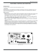
Ratio Diversity Receiver REAR PANEL CONTROLS AND FUNCTIONS ANTENNA INPUTS hese inputs connect to any 50 ohm antenna with a BNC type connector. 12 VDC INPUT This input connects to the supplied CH-12 AC adapter for powering the receiver from a 110/120V AC source. The receiver may also be powered from external 12 volt DC sources using the correct plug (Switchcraft S-760 power plug). The center pin is positive. (+).
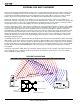
ANTENNA USE AND PLACEMENT There are two antennas included with this receiver. One is a telescoping whip that connects to either terminal on the rear panel of the DR185 receiver. The other antenna is a coaxial type for use away from the receiver. This remote coaxial antenna should be positioned so that the stripped end of the coaxial cable is at least 4 or 5 feet (1/2 wave length or more) away from the whip antenna. This will insure the maximum benefit of the diversity circuitry.
Ratio Diversity Receiver OPERATING INSTRUCTIONS 1) Connect the power supply. 2) Attach and place the antennas. 3) Connect the audio cable. 4) Set the front panel switch to the “MUTE” position. Check to see that the red POWER LED lights up (the leftmost LED in the 9-LED display). 5) Adjust the transmitter “gain”. THIS IS PERHAPS THE MOST IMPORTANT STEP IN THE SET UP PROCEDURE.
TROUBLESHOOTING Before going through the following chart, be sure that you have a good battery in the transmitter and that the transmit ter power LED is indicating normally.
Ratio Diversity Receiver SPECIFICATIONS AND FEATURES Operating frequencies: 150 to 216 MHz, crystal controlled Sensitivity: Better than 0.5uV for 20 dB quieting without compandor; 1.7uV for 50dB S/N ratio with compandor Signal/noise ratio: 96 dB flat; 99 dB A-weighted Squelch quieting: Greater than 110 dB AM rejection: -60 dB (10uV to 0.
SERVICE AND REPAIR If your system malfunctions, you should attempt to correct or isolate the trouble before concluding that the equipment needs repair. Make sure you have followed the setup procedure and operating instructions. Check out the intercon necting cords and then go through the TROUBLE SHOOTING section in the manual We strongly recommend that you do not try to repair the equipment yourself and do not have the local repair shop attempt anything other than the simplest repair.
LIMITED ONE YEAR WARRANTY The equipment is warranted for one year from date of purchase against defects in materials or workmanship provided it was purchased from an authorized dealer. This warranty does not cover equipment which has been abused or damaged by careless handling or shipping. This warranty does not apply to used or demonstrator equip ment. Should any defect develop, we will, at our option, repair or replace any defective parts without charge for either parts or labor.