DR175 COMPACT RECEIVER OPERATING INSTRUCTIONS and trouble-shooting guide Digital Code Squelch LECTROSONICS, INC.
INTRODUCTION Thank you for selecting the Lectrosonics system. The DR175 represents over 70 years of combined experience in the design of RF and audio devices and sets new standards for RF performance and flexibility. This receiver utilizes a “maximal ratio combining” technique, providing a very effective type of diversity reception. This is the first high performance receiver on the market to utilize this technique to combine the outputs of two separate receivers without hard-switching.
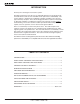
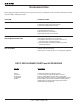
Ratio Diversity Receiver FRONT PANEL CONTROLS AND FUNCTIONS MODULATION INDICATORS Two (2) LEDs indicate the audio level (modulation) of the incoming signal, which are typically used for proper adjustment of the transmitter’s “MIC LEVEL” or “GAIN”. The -20 LED (green) lights during normal modulation. The 0dB (red) LED indicates maximum modulation and that the transmitter audio input may be “limiting.” Occasional flickering of this LED is normal. It should not stay on for long periods, however.
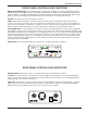
ANTENNA USE AND PLACEMENT There are two antennas included with this receiver. The A170 AC is a whip antenna that connects to either terminal on the rear panel of the DR175 receiver. Position the antennas so that they are not within 3 or 4 feet of large metal surfaces. If this is not possible, try to position the antennas so that they are as far away from the metal surface as is practical.
Ratio Diversity Receiver OPERATING INSTRUCTIONS 1) Connect the power supply. 2) Attach and place the antennas. 3) Connect the audio cable. 4) Set the front panel AUDIO LEVEL control fully counter-clockwise and set the POWER switch to ON. Check to see that the red POWER LED lights up. 5) Adjust the transmitter “gain”. THIS IS PERHAPS THE MOST IMPORTANT STEP IN THE SET UP PROCEDURE.
TROUBLESHOOTING Before going through the following chart, be sure that you have a good battery in the transmitter and that the transmit ter power LED is indicating normally.
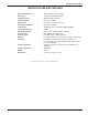
Ratio Diversity Receiver SPECIFICATIONS AND FEATURES Operating frequencies: Sensitivity: Signal/noise ratio: Squelch quieting: AM rejection: Modulation acceptance: IF Selectivity: Third order intercept: Diversity technique: Audio outputs: Antenna inputs: Controls: Indicators: Power requirements: Power consumption: Weight: Dimensions: 150 to 216MHz, crystal controlled -110dBm for 20dB Sinad (0.
SERVICE AND REPAIR If your system malfunctions, you should attempt to correct or isolate the trouble before concluding that the equipment needs repair. Make sure you have followed the setup procedure and operating instructions. Check out the intercon necting cords and then go through the TROUBLE SHOOTING section in the manual We strongly recommend that you do not try to repair the equipment yourself and do not have the local repair shop attempt anything other than the simplest repair.
Ratio Diversity Receiver This page intentionally blank.
LIMITEDONE ONE YEAR LIMITED YEARWARRANTY WARRANTY The equipment is warranted for one year from date of purchase against defects in materials or workmanship provided it was purchased from an authorized dealer. This warranty does not cover equipment which has been abused or damaged by careless handling or shipping. This warranty does not apply to used or demonstrator equipment. Should any defect develop, Lectrosonics, Inc.