
User's Manual
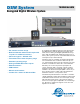

DR Receiver Rear Panel
DR Receiver Front Panel
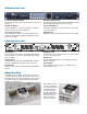
Modular Versatility
Individual receiver modules are nested on both sides
of the mainframe assembly. The modules tune across a
25.6 MHz range and can be positioned in any of the six
pockets in the chassis. Delrin retaining clips keep the
modules securely in place.
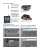
Front Panel Antenna Mounts
Convenient when the receiver is installed in a rack mount
transit case.
Headphone Monitor
Monitor individual or a mix of any number of channels.
Volume knob recesses into from panel.
LCD and Control Panel
Easy navigation of numerous setup parameters is pro-
vided by a backlit LCD, membrane pushbuttons and a
rotary control wheel.
Encryption Key Interface
Encryption key transfer and complete transmitter setup is
accessed through a TRS mini-jack connection.
Front Panel USB Port
A standard USB interface is provided on the front panel
for the PC interface.
LED Indicators
Operational and power status is indicated by three LEDs.
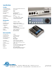
Antenna Ports
Antenna inputs and outputs to an additional mainframe
allow “stacking” of up to three mainframes with a single
pair of antennas.
Audio Outputs
Six XLR jacks provide analog and AES-EBU outputs in
various configurations as labeled on the rear panel.
Ethernet Port
Network connection is provided through a standard RJ-
45 jack.
AES Word Clock
The mainframe can provide the master clock sync signal,
or sync to an external clock.
RS-232 Port
Control with third party devices is enabled through an
RS-232 serial port.
Power Supply
The mainframe is powered by 10 to 18 VDC from an
external 4 amp source.
( )
( )
AES
WORD
CLOCK
ANT
PWR
AES
5 & 6
AES
3 & 4
AES
1 & 2
ANT
PWR
The modules are fan
cooled for reliable op-
eration when installed
in racks with limited
ventilation. Unused
modules installed in
the mainframe can be
powered on and off
with the software or
front panel controls.