
Instruction Manual


DPR-A
LECTROSONICS, INC.
12
Setup Screen Details
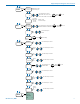
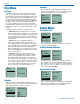
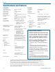
Main Window Indicators
The Main Window displays the operating frequency,
Standby or Operating mode, battery status, if an
SDHC card is presnt/recording, and audio level.
DPr
00 : 02 : 37
-20
+0
470.100
-40
Frequency (MHz)
Operating mode
Battery status
Audio level
Indicates micro
SDHC card
present and
recording status
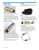
Connecting the Signal Source
Microphones, line level audio sources, and instruments
can be used with the transmitter. Refer to the section
entitled Input Jack Wiring for Different Sources for
details on the correct wiring for line level sources and
microphones to take full advantage of the Servo Bias
circuitry.
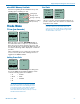
Turning Control Panel LEDs ON/OFF
From the main menu screen, a quick press of the UP
arrow button turns the control panel LEDs on. A quick
press of the DOWN arrow button turns them off. The
buttons will be disabled if the LOCKED option is se-
lected in the Setup menu.
The control panel LEDs can also be turned on and off
with the LED Off option in the Setup menu.
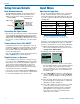
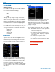
Helpful Features on Receivers
To aid in finding clear frequencies, several Lectroson-
ics receivers offer a SmartTune feature that scans the
tuning range of the receiver and displays a graphical
report that shows where RF signals are present at
different levels, and areas where there is little or no
RF energy present. The software then automatically
selects the best channel for operation.
Lectrosonics receivers equipped with an IR Sync func-
tion allow the receiver to set frequency on the transmit-
ter via an infrared link between the two units.
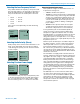
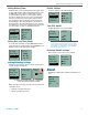
Input Menu
Adjusting the Input Gain
The two bicolor Modulation LEDs on the control panel
provide a visual indication of the audio signal level
entering the transmitter. The LEDs will glow either red
or green to indicate modulation levels as shown in the
following table.
Signal Level -20 LED -10 LED
Less than -20 dB
Off Off
-20 dB to -10 dB
Green Off
-10 dB to +0 dB
Green Green
+0 dB to +10 dB
Red Green
Greater than +10 dB
Red Red
NOTE: Full modulation is achieved at 0 dB,
when the “-20” LED first turns red. The limiter
can cleanly handle peaks up to 30 dB above this
point.
It is best to go through the following procedure with the
transmitter in the standby mode so that no audio will
enter the sound system or recorder during adjustment.
1) With fresh batteries in the transmitter, power the
unit on in the standby mode (see previous section
Turning Power ON and OFF).
2) Navigate to the Gain setup screen.
Input...
Gain
Rolloff
Phase
-40
-20
+0
Gain
22
3) Prepare the signal source. Position a microphone
the way it will be used in actual operation and have
the user speak or sing at the loudest level that
will occur during use, or set the output level of the
instrument or audio device to the maximum level
that will be used.
4) Use the and arrow buttons to adjust the gain
until the –10 dB glows green and the –20 dB LED
starts to flicker red during the loudest peaks in the
audio.
5) Once the audio gain has been set, the signal can
be sent through the sound system for overall level
adjustments, monitor settings, etc.
6) If the audio output level of the receiver is too high
or low, use only the controls on the receiver to
make adjustments. Always leave the transmitter
gain adjustment set according to these instruc-
tions, and do not change it to adjust the audio
output level of the receiver.