
Manual


DM Series Installation Guide
Rio Rancho, NM
7
SincethecalculatedVphisequaltoVphfromthe
microphone specification sheet, this is a marginal situ-
ation.
Microphone Number 2:
FromSpecicationSheet: V
ph
(min) = 9 V
I
mic
(max.) = 2 mA
V
ph
=15V-(1k)(.002A)
V
ph
=15V-2V=13 V
SincethecalculatedVphisgreaterthantheVphfrom
the microphone specification sheet, this is an accept-
able situation.
Audio Outputs
All outputs are a balanced differential configuration.
Some outputs include an attenuator to reduce the sig-
nal to mic level. Use the outputs marked as MIC/LINE
OUTPUTS for mic level applications. Using the other
outputs marked LINE OUTPUTS with control panel at-
tenuation can result in up to 40 dB of additional noise.
NOTE: Using a Line Output with digital attenuation
applied with the Control Panel to achieve Mic Level
will result in added noise.
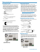
When the DM output is connected to a balanced input,
wire it as indicated in DM Out to Balanced Input (3-
Wire). Select Mic or Line (as appropriate) either from
the front panel LCD interface or via the software GUI.
When the DM output is conencted to an unbalanced
input, wire it as indicated in DM Out to Unbalanced
Input (3-Wire), or DM Out to Unbalanced Input (2-
WIre).
DM Out
+
-
Destination
+
-
DM Out to Balanced Input
(3-Wire)
Shield
DM Out
+
-
Destination
+
DM Out to Unbalanced Input
(3-Wire)
Shield
DM Out
+
-
Destination
+
DM Out to Unbalanced Input
(2-Wire)
Shield
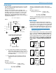
Phantom Power
TheDMsupplies+15VDCphantompowertotheaudio
inputs via a programmable switch and two 2 k resistors.
(See illustration below.)
However, the true phantom power available at the
microphone may be less due to voltage drop across the
microphone itself (source resistance). In some cases,
the voltage drop may be enough to result in marginal
performance. The following formula can be used to
determine how much phantom power will be available to
a particular microphone.
V
ph
=15V-(1k)(I
mic
)
Where:
V
ph
= the actual voltage available at the microphone.
(Microphone specifications list this as the mini-
mum recommended phantom voltage value. To
minimizeproblems,thecalculatedVphshould
exceed this value.)
I
mic
= the current draw of the microphone. (Refer to
individual microphone specifications for this
value.)
Examples:
Microphone Number 1;
FromSpecicationSheet: V
ph
(min) = 11 V
I
mic
(typical) = 4 mA
V
ph
=15V-(1k)(.004A)
V
ph
=15V-4V=11 V
+15V
Phantom On/Off
(from Micro Controller)
Gain Control
(from Micro Controller)
0, 10, 20, 30, 40, 50 dB
RF Filter
and
AC Coupling
2 kohm 2 kohm
To CODEC
Pin 2 or 4
Pin 1 or 5
Pin 3
PGA
+
-
+
-
+
-
Chassis GND Analog GND
Programmable Gain Preamplifiers with
Software Switchable Phantom Voltage
+15 VDC
2k
2k
To
PGA
Equivalent Circuit
Phantom On/Off