
User's Manual

DCHT, DCHT/E01
LECTROSONICS, INC.
16
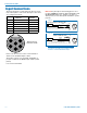
Input Connections
The 6-pin input jack accommodates two discrete chan-
nels at microphone or line levels. The input connections
are configured as follows:
ANALOG DIGITAL
Pin 1 CH 1 Shield/Gnd AES GND
Pin 2 CH 1 Mic level
Pin 3 CH 1 Line level
Pin 4 CH 2 Mic level AES CH 1
Pin 5 CH 2 Shield/Gnd AES CH 2
Pin 6 CH 2 Line level
1
2
3
4
5
6
TA6FLX connector
viewed from outside
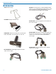
Refer to the Accessories section of this manual for
details on the available adapter cables.
The mating connector for the DCHT, DCHT/E01 in-
put jack is a Switchcraft TA6FLX 6-pin female (nickel
plated).
Lectrosonics P/N 21932.
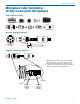
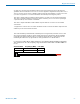
NOTICE: Any microphone wired using pin 2 for elec-
tret bias will NOT work with the DCHT, DCHT/E01 and
MCTA6TA5M2 adapter. For example, see figures 1
and 2 (below) for servobias inputs that will not operate
properly.
1
2
3
4
5
PIN
SHIELD
AUDIO
1
2
3
4
5
TA5F
PLUG
2.7 k
2 VOLT NEGATIVE BIAS 2-WIRE ELECTRET
Compatible wiring for microphones
such as negative bias TRAM models.
NOTE: The resistor value can range from 2k to 4k ohms.
Fig. 2
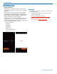
Fig. 1
1
2
3
4
5
PIN
SHIELD
A UDI O
1
2
3
4
5
T A5 F
PLUG
3.3 k
1.5 k
2 VOLT POSITIVE BIAS 2-WIRE ELECTRET
Compatible wiring for microphones such as
Countryman E6 headworn and B6 lavaliere.
Also see Fig. 9
NOTE: The Sanken CUB-01 is wired using pin
2 for the bias and will not work with the DCHT,
DCHT/E01 and MCTA6TA5M2 adapter.