
User's Manual

DCHT, DCHT/E01
LECTROSONICS, INC.
10
Input Menu
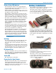
Adjusting the Input Gain for Analog Inputs
For analog gain adjustment, two multi-color LEDs on
the top panel, one for each channel, provide a visual
indication of the audio signal level entering the transmit-
ter. The LEDs will glow either red or green to indicate
modulation levels as shown in the following table.
Signal Level CH1 CH2
Less than -20 dB
Off Off
-20 dB to +0 dB Green Green
+0 dB and greater Red Green
NOTE: This procedure is used for analog inputs
only. AES digital input is factory set at the industry
standard level. The LEDs on the top panel will glow
blue when the audio level reaches about -40 FS.
It is best to go through the following procedure with the
transmitter in the standby mode so that no audio will en-
ter the sound system or recorder during adjustment.
1) With fresh batteries in the transmitter, power the
unit on in the standby mode (see previous section
Powering On in Standby Mode).
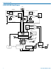
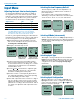
2) Navigate to the Gain setup screen.
Input...
Gain
Rolloff
StMode
-40
-20
0
Gain
25
-40
-20
0
Gain
25
20
21
Setup screen in
Linked mode
Setup screen in
Independent mode
3) Position a microphone the way it will be used in
actual operation and have the user speak or sing
at the loudest level that occur during use, or set the
output level of the audio device to the maximum
level that will be used.
4) Use the and arrow buttons to adjust the gain
until the LED glows green most or all of the time,
and flicker red during the loudest peaks.
5) Turn the recorder or sound system gain down be-
fore setting the transmitter to the normal operating
mode and enabling the audio output.
6) If the audio output level of the receiver is too high or
low, use only the controls on the receiver to make
adjustments. Always leave the transmitter gain ad-
justment set according to these instructions, and do
not change it to adjust the audio output level of the
receiver.
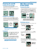
Selecting the Low Frequency Roll-off
The low frequency audio roll-off is adjustable to op-
timize performance for ambient noise conditions or
personal preference.
Low frequency audio content may be desirable or
distracting, so the point at which the roll-off takes place
can be set at 20, 35, 50, 70, 100, 120 and 150 Hz.
Rolloff
70 Hz
Input...
Gain
Rolloff
StMode
Rolloff
70
Hz
21
70
Hz
Setup screen in
Linked mode
Setup screen in
Independent mode
Selecting StMode (stereo mode)
The two channels can be set to Indep (independent) or
Linked. Indep allows the gain to be adjusted separately
on each channel. Linked employs the gain adjustment
to both channels.
StMode
Indep
Linked
Input...
Gain
Rolloff
StMode
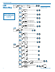
Selecting Input Type
AES digital or analog audio input is selected with the
InType menu item. With the AES selected, there are no
additional settings needed for the input. Analog input
configuration is set with the InpCfg1 and InpCfg2
menu items.
Input...
InType
InpCfg1
InpCfg2
InType
Analog
AES
Selecting Input Configuration
When the input type is set to Analog, InpCfg1 and
InpCfg2 menus are used to configure the audio input
for the respective channels. Use the and arrow
buttons to select the input type.
Input...
InType
InpCfg1
InpCfg2
InpCfg1
Line In
InpCfg2
Oth Lav